|
The proposal for the 28 chimney cap/shrouds:
(10/05 - 3/06)
|
|
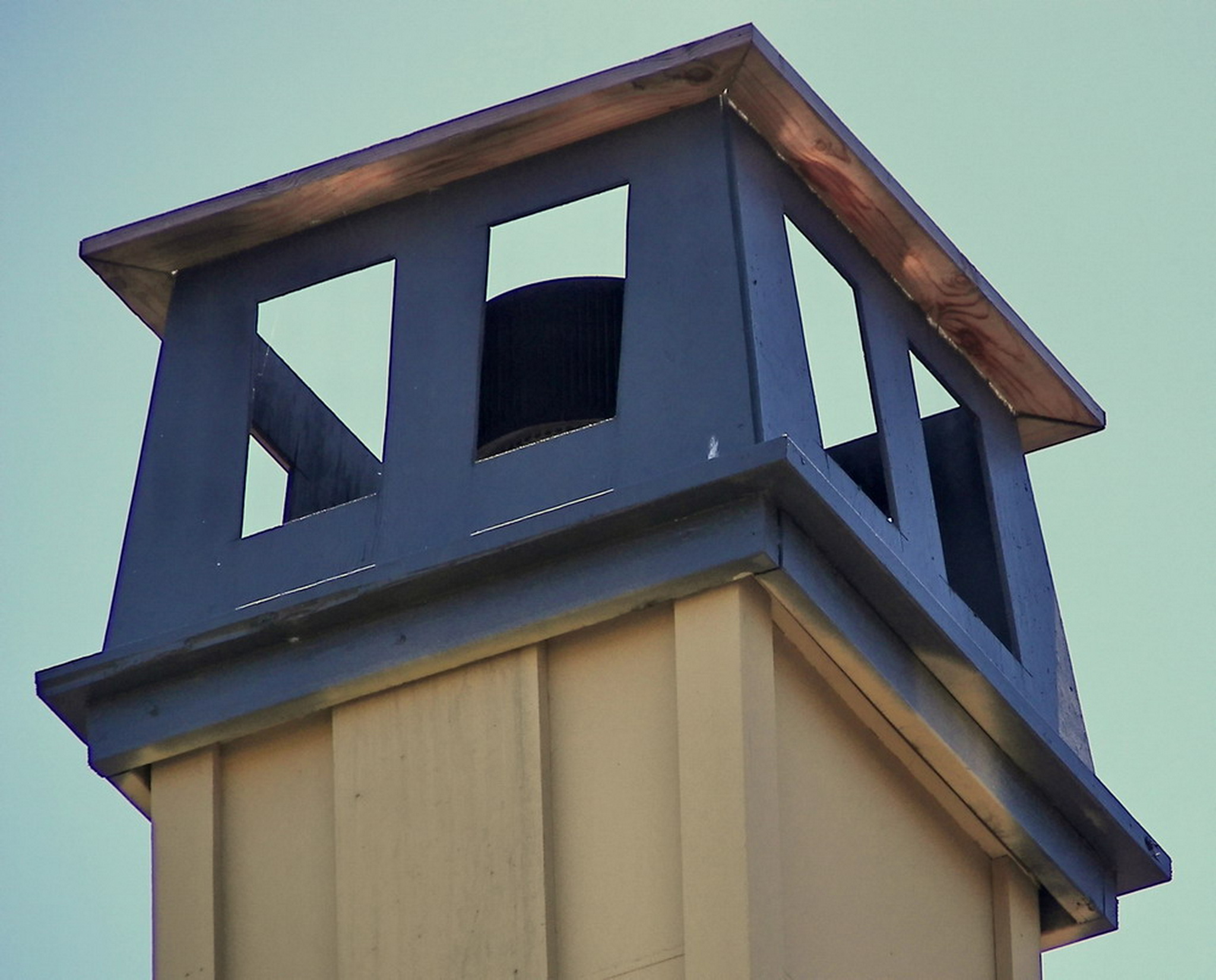
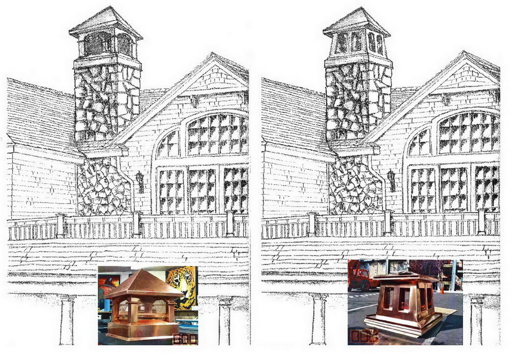
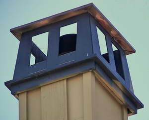
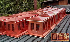
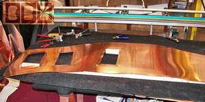
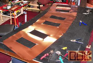
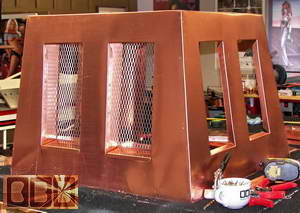
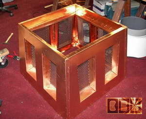
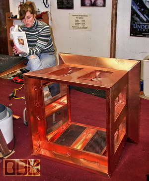
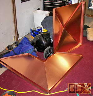
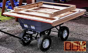
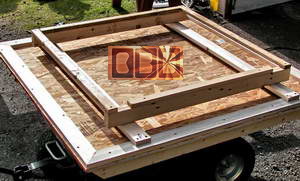
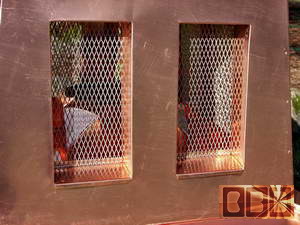
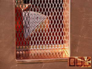
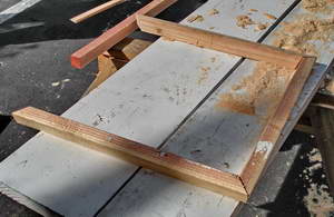
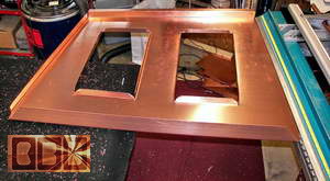
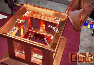
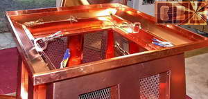
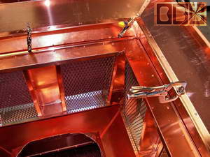
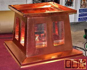
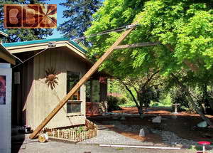
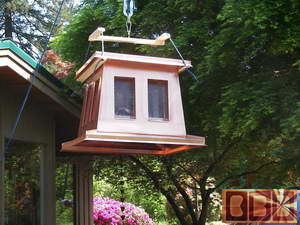
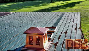
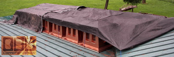
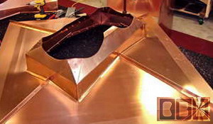
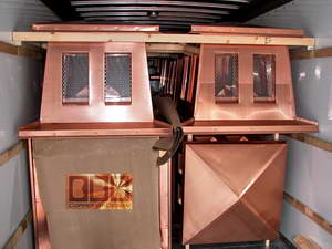
This chimney shroud project
was designed by
RSS Architecture. They had built this
full size wood model of their design and mounted it to show their clients:
Northwestern Mutual
and Prometheus Real Estate Group
Kensington Fair Oaks Associates Joint Venture just
how it would look from the ground .
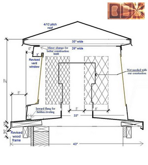
Through e-mail they sent
us a diagram and these photos for a quote on the 28 chimney cap project
for the apartment complex they were working on. We exchanged several
revised diagrams over the next few months to come up with the final
design shown below, but they opted for a little lower profile roof,
so there is less chance the roof of these chimney caps would be seen
from the ground.
|
|
The final delivery
of the last 27 Chimney Caps ordered:
To: Sunnyvale, California
(6/06)
|
|
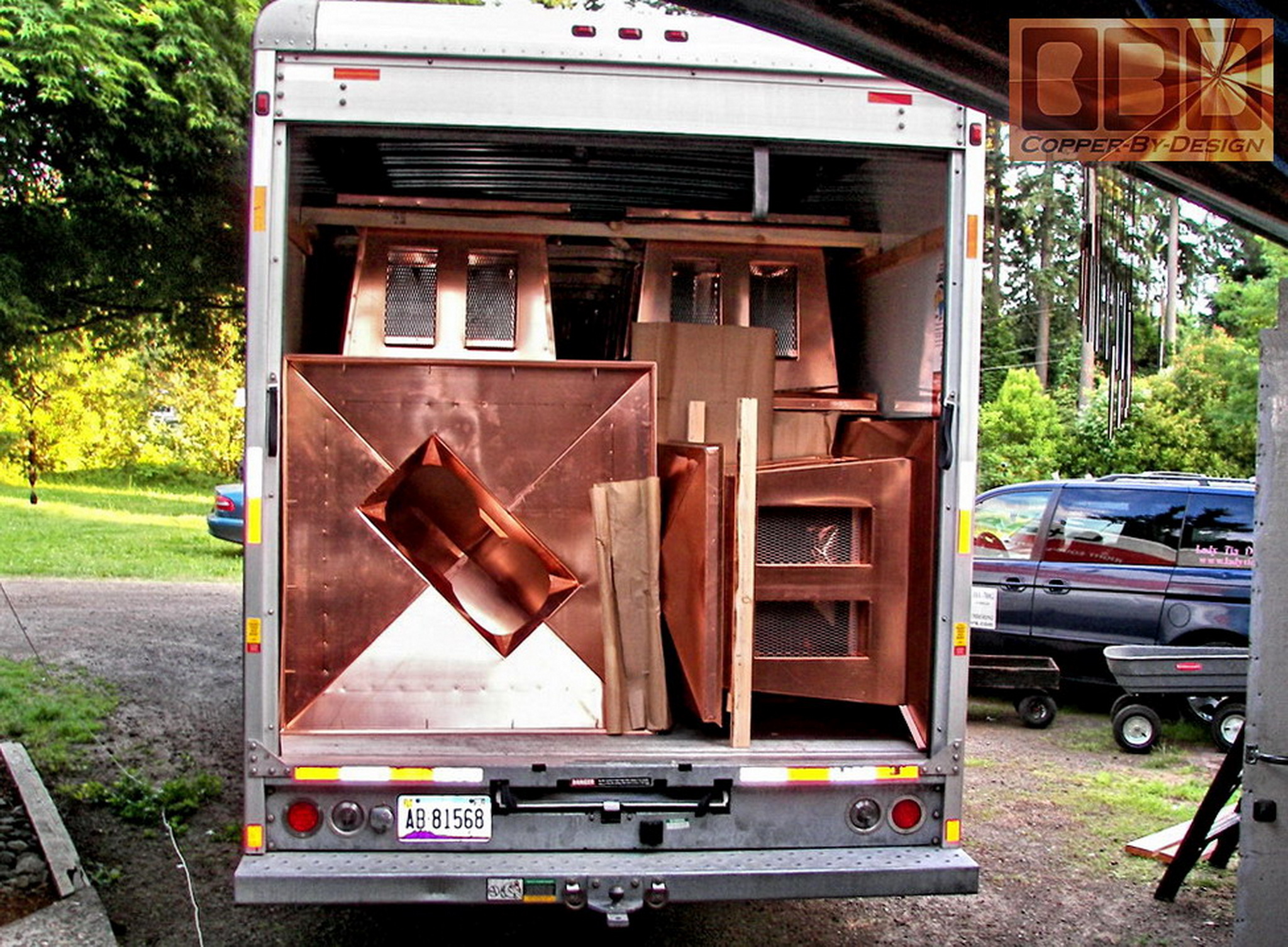
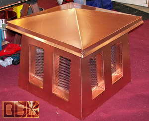
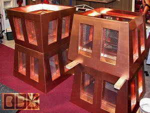
We've were finally contracted
to build these 28 copper chimney cap/shrouds with 18 gauge stainless
steel screens. We shipped one unit to the client for review and placement
to see if any alterations would need to be made, before we continued
to build the 27 additional units.
 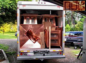
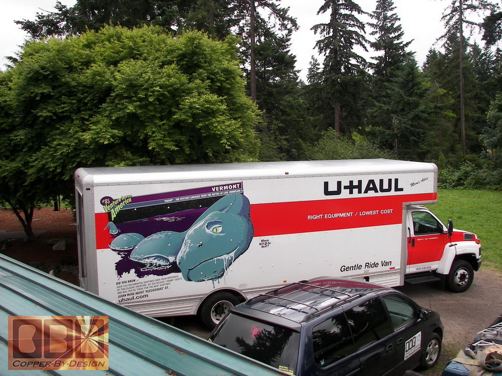
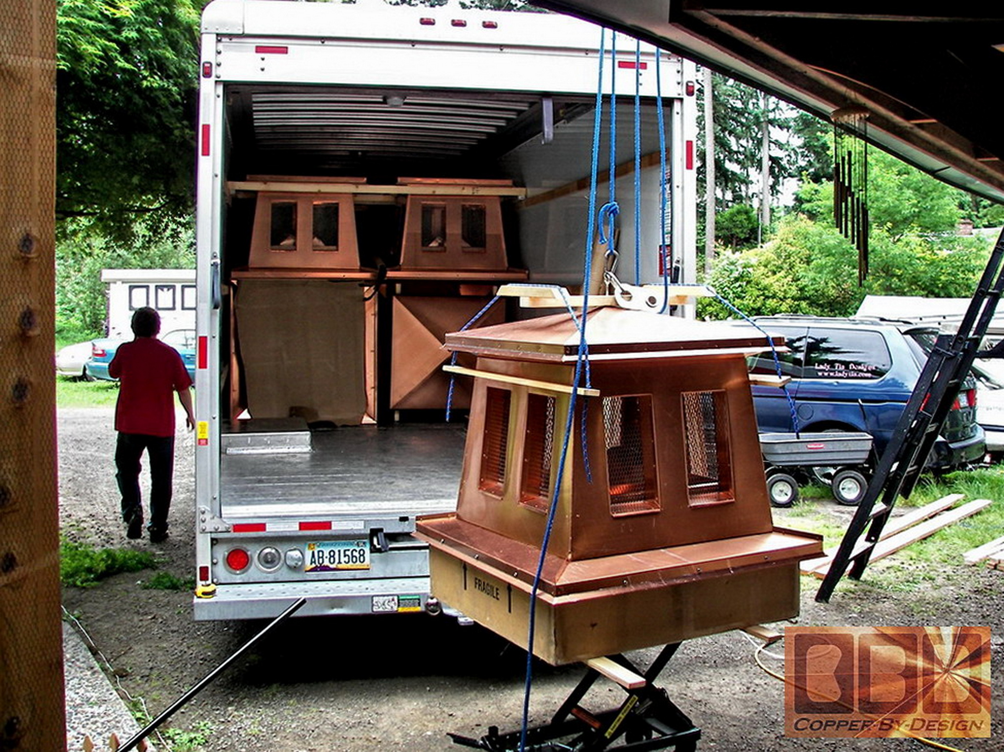
We negotiated a much lower
shipping cost by agreeing to driving the rest down personally to Sunnyvale
California in the largest U-haul truck they rent. They all just barely
fit. I was almost thinking I would have to rope one on the outside of
the back door.
Cost: $45,279.20 for 28 delivered
26 at $1,531.11 ea. + 2 larger double flue units
|
|
What our competition had to offer:
|
|
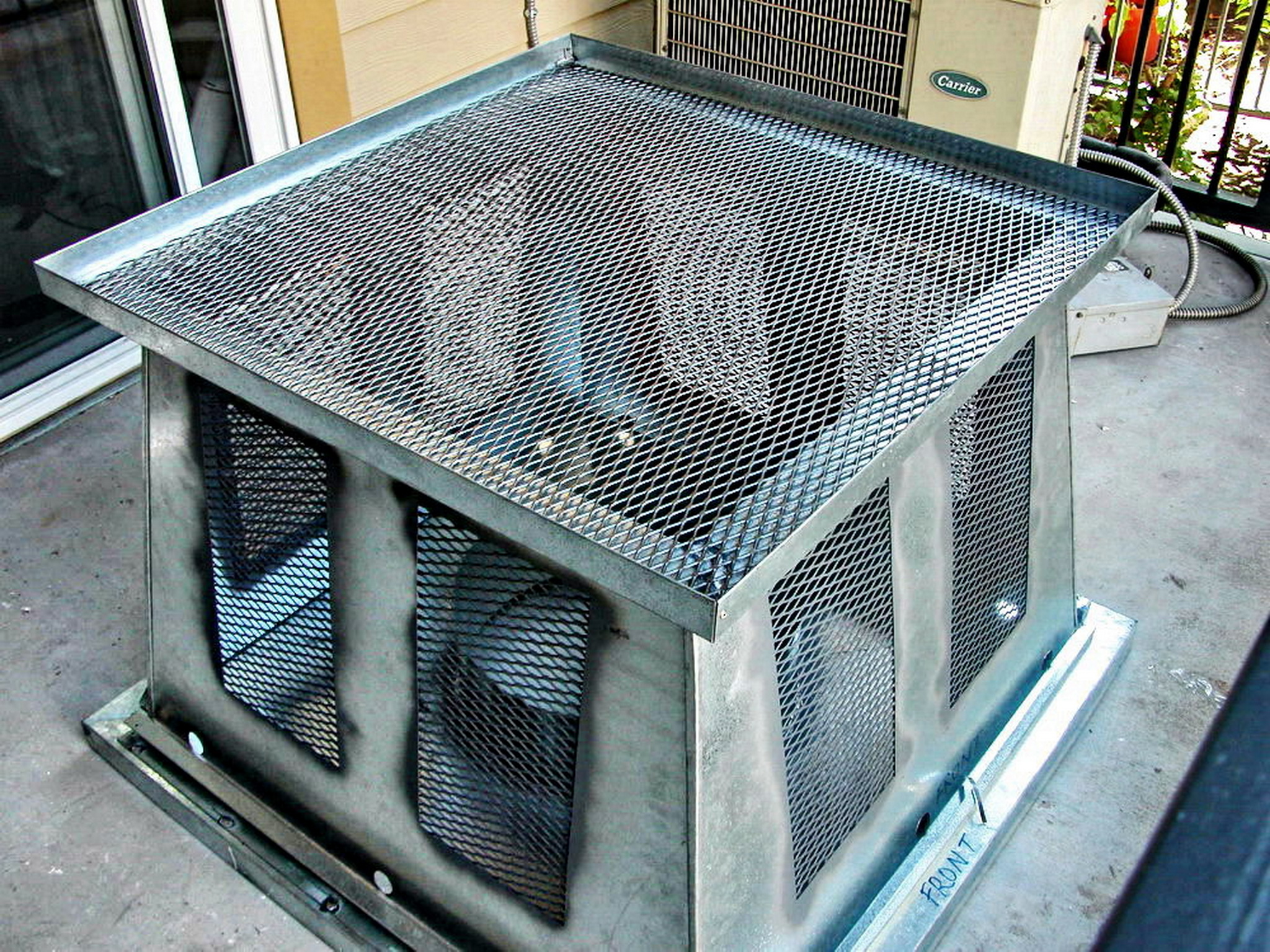
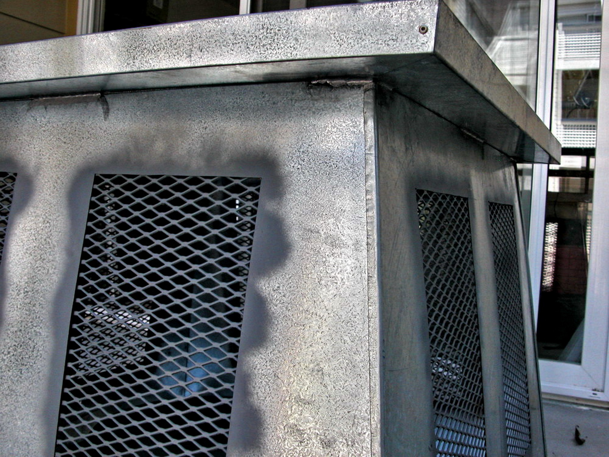
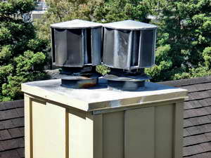
This galvanized
steel chimney cap is NOT what we made:
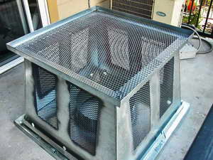 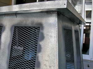
Before having found our
web site and contacting us they had this galvanized steel shroud built
by a local California sheet metal shop. It was built with cheap
galvanized steel that was simply spot welded together with a few rivets
to help hold some of the seams in place for the spot welding.
|
|
Working out
the design and contract for these 28 chimney caps:
|
|
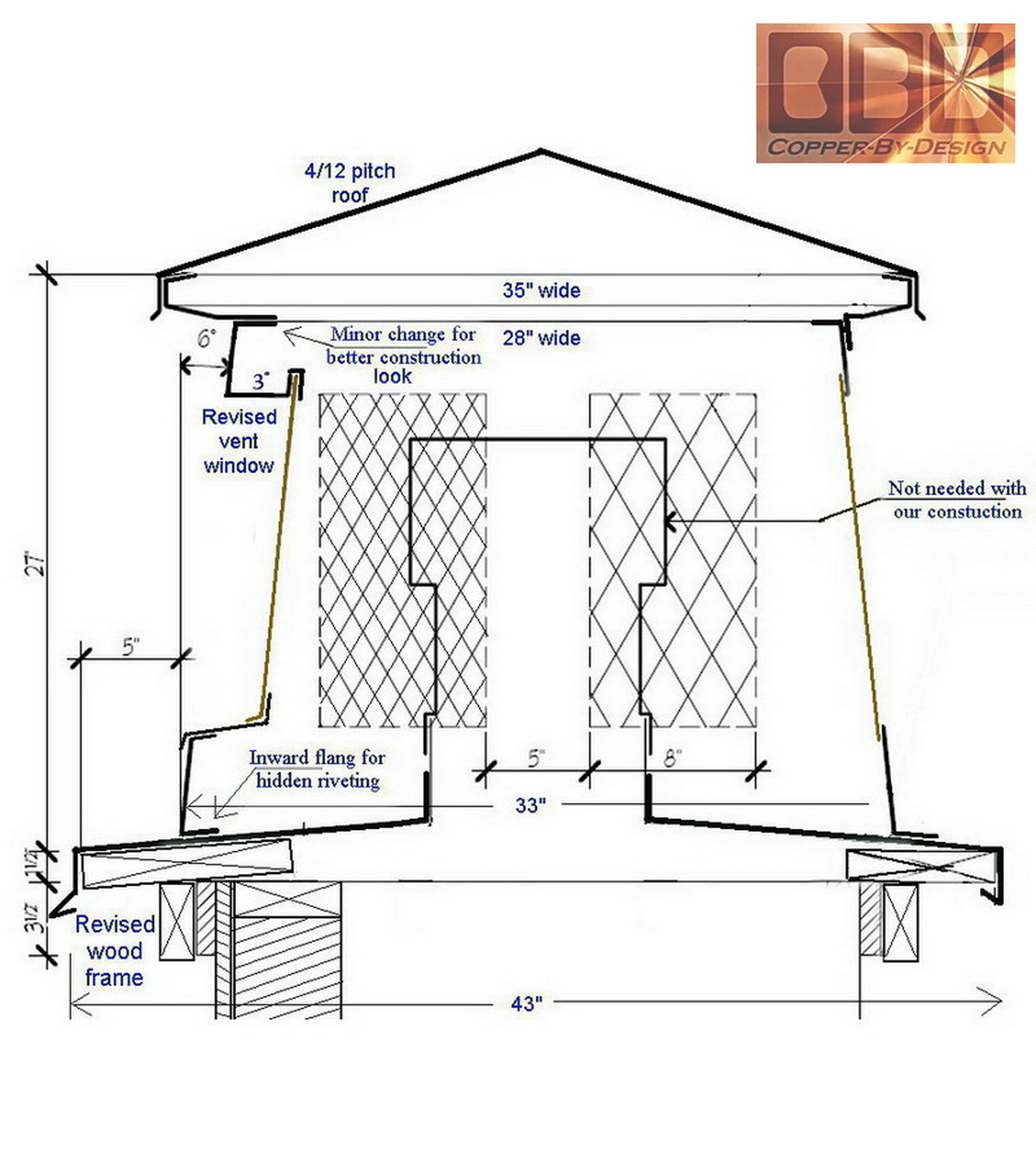
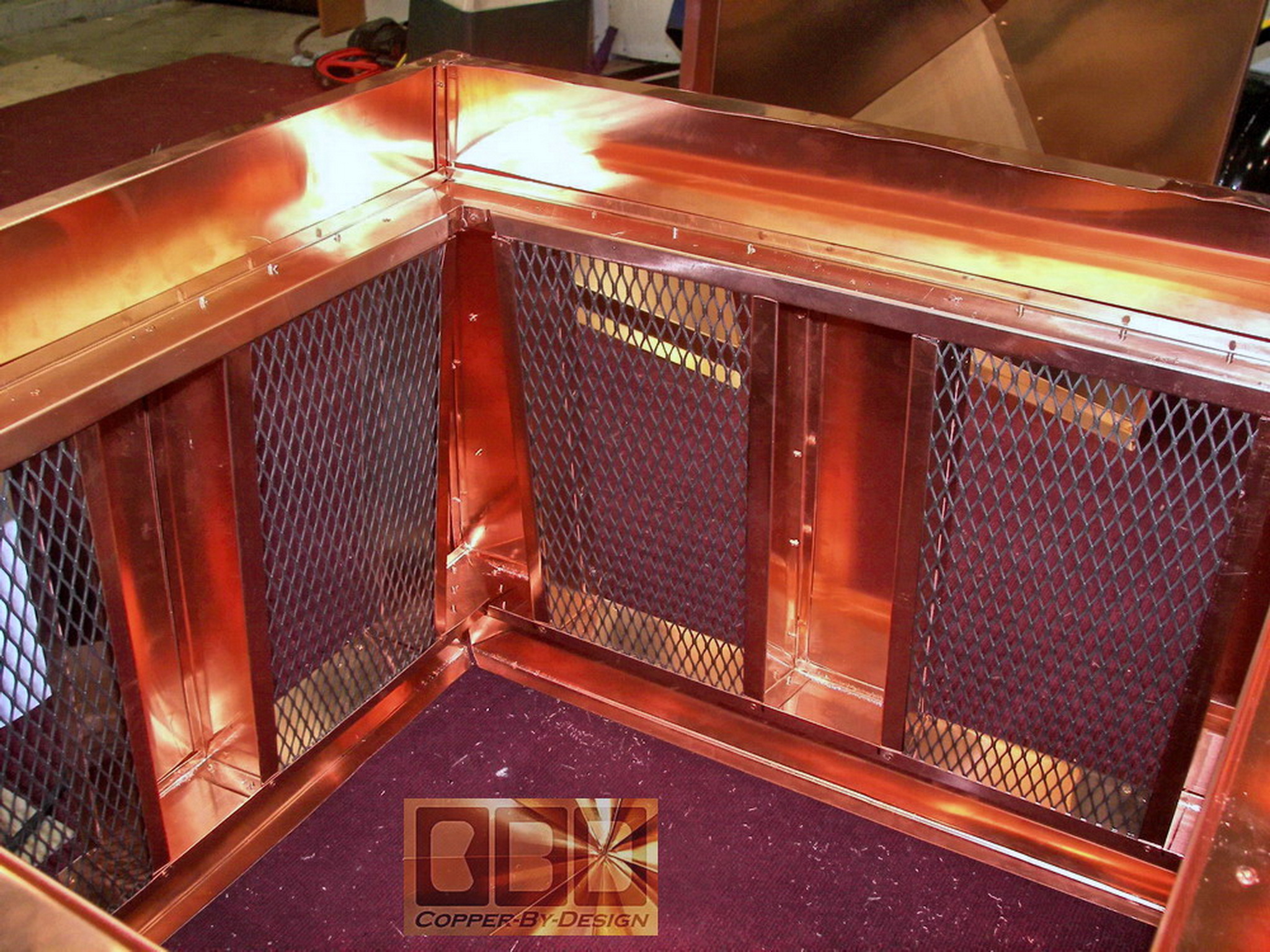
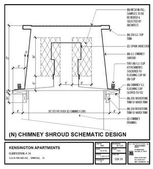
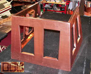
In researching further, they came across our web
site and contacted us for a quote. We offered
some modifications to improve it's functionality and looks with adding
a sealed roof over the top and 3" deep set inner walls for the side
screened vents to add strength structurally as well as visually. It
took several diagram revisions to get the final design locked down over
the coarse of a couple months. Our modified version was
made with a low profile 3/12 pitch hipped roof that would not change
the appearance much from the ground. Without a roof cover this shroud
would be nothing more than a decoration.
With our suggestion of making these with
a roof and a 3" deep inset screened vents (instead of just simply flush
like you saw in the steel version above), it would take about twice
the metal to form these chimney caps. They liked
the ideas I had offered, but at the cost of over $1,500 each, which
was over 3 times the cost of that steel one they had built before contacting
us. They asked for a comparison bid if we we worked in steel,
knowing that we wouldn't. They just wanted to compare apples to apples
here. You can read our response by going back to the
#3 Chimney Cap
page.
|
|
Working up the design into fabrication: (3/8/06)
|
|
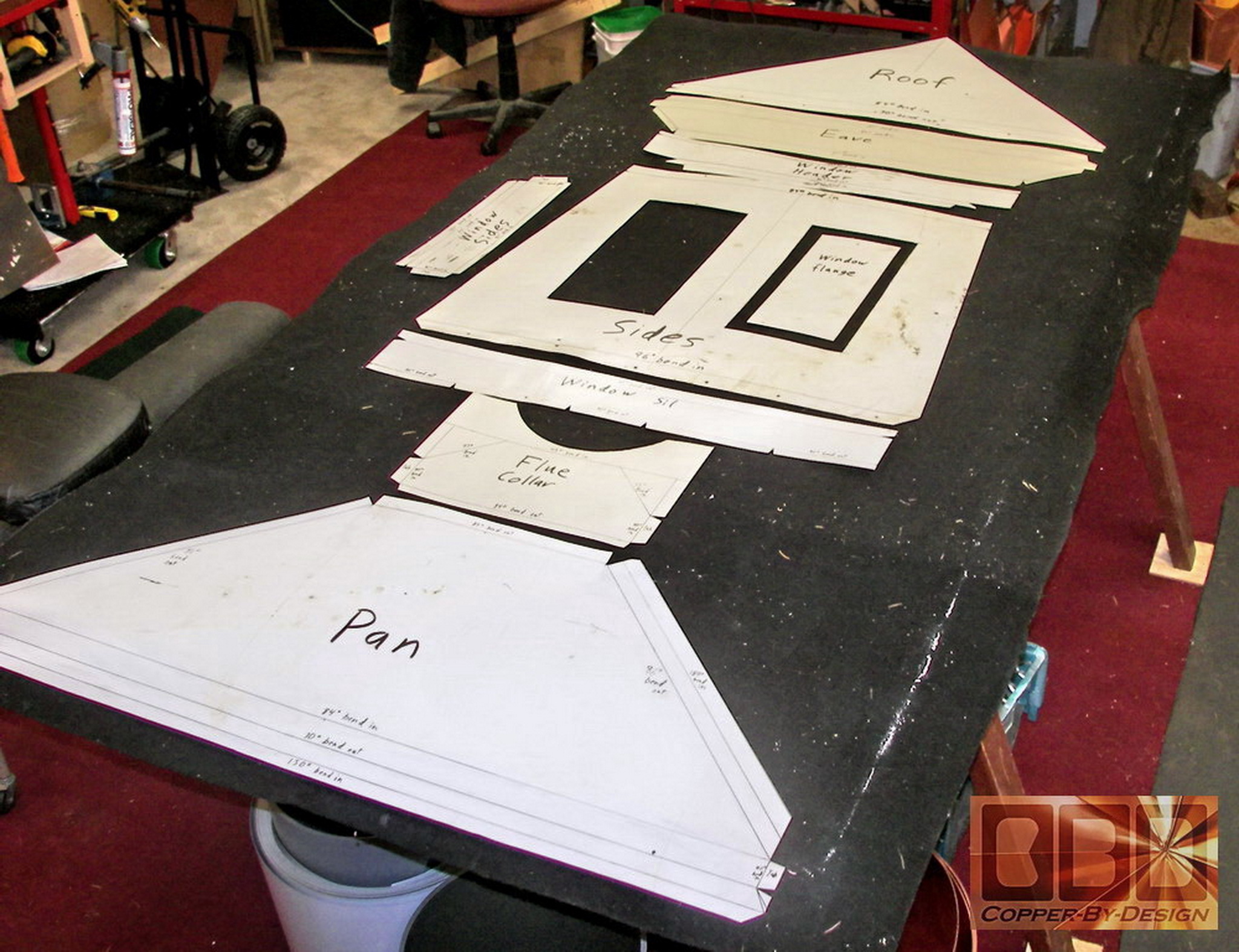
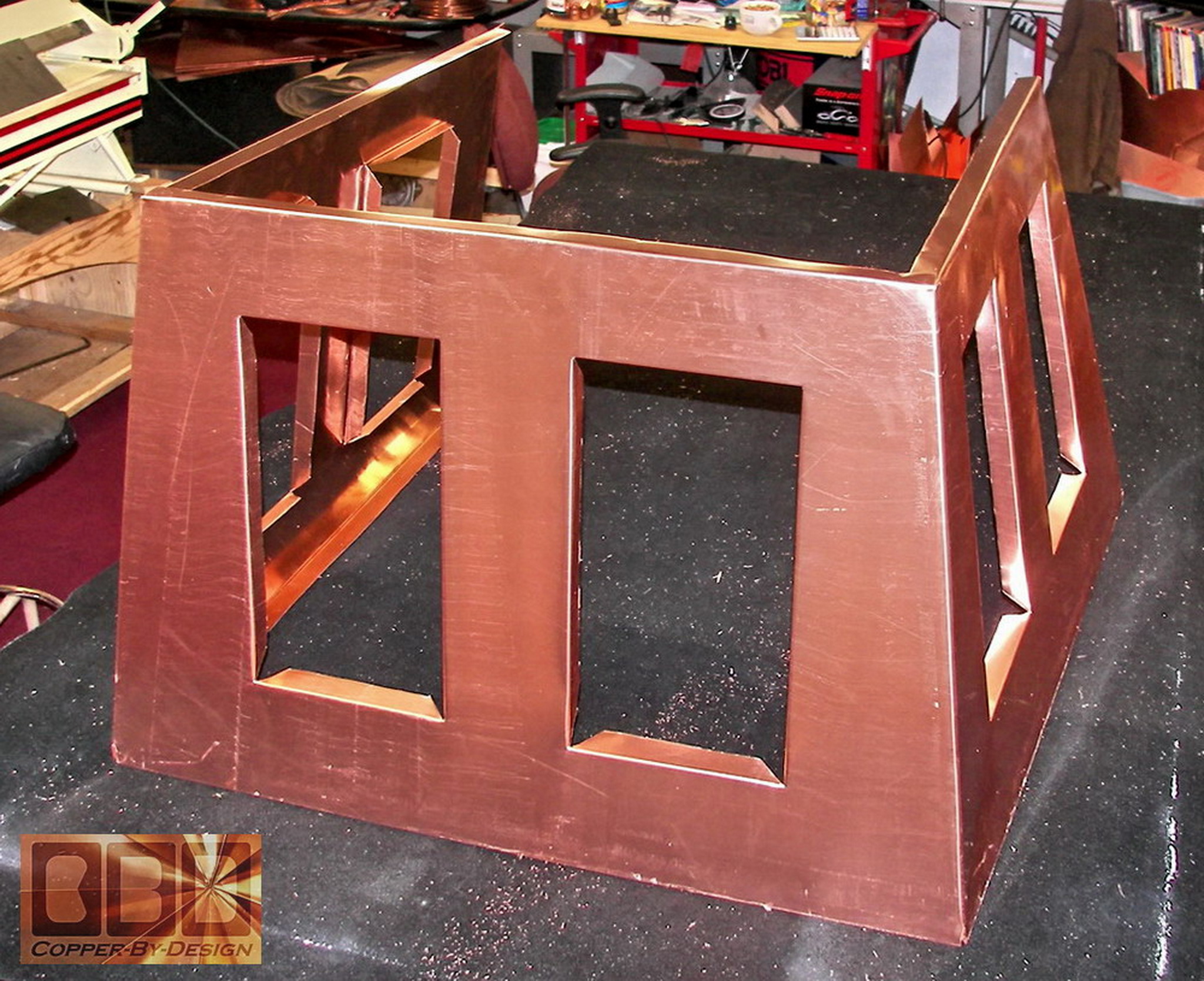
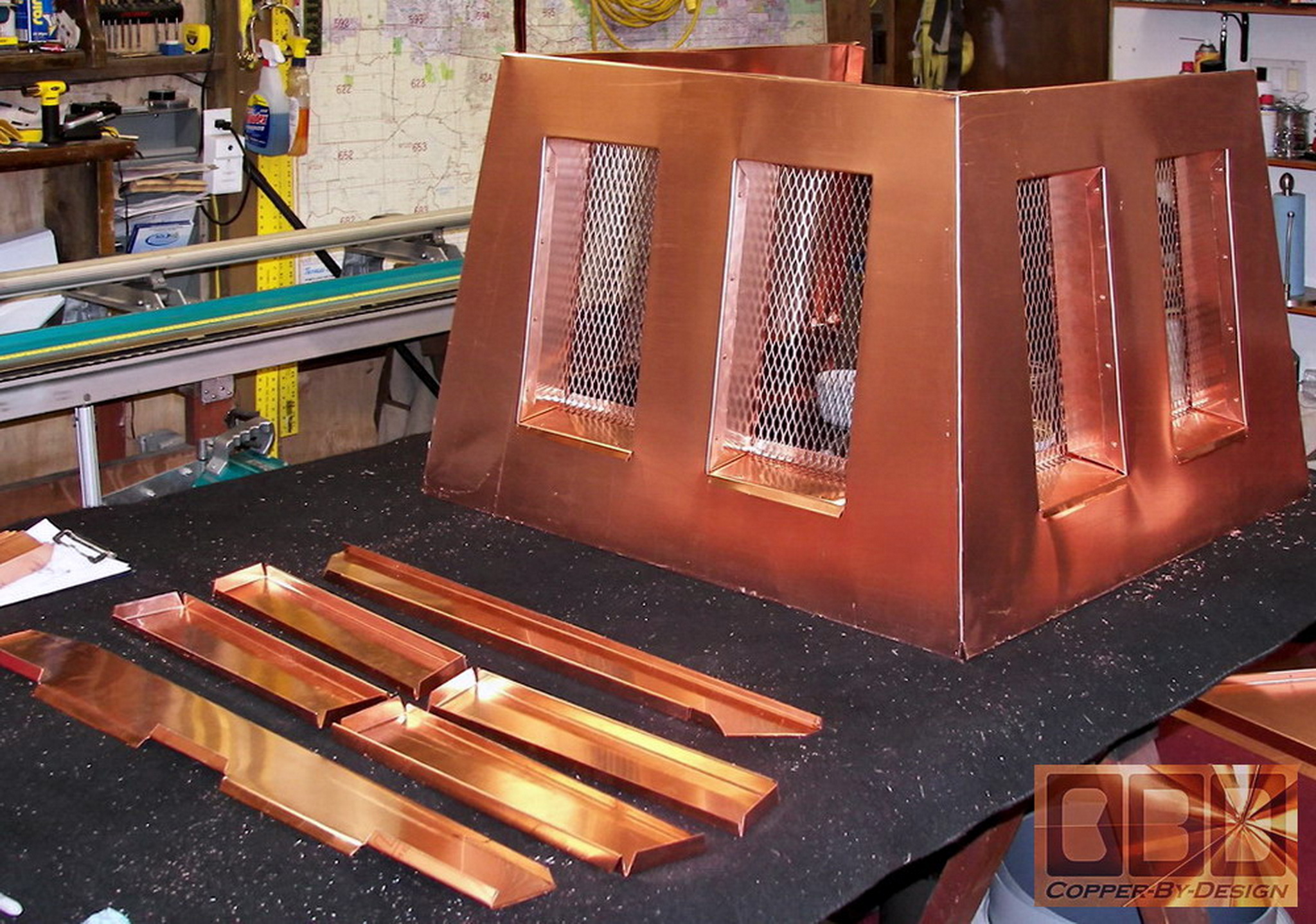
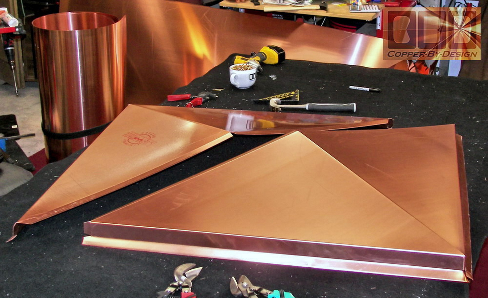
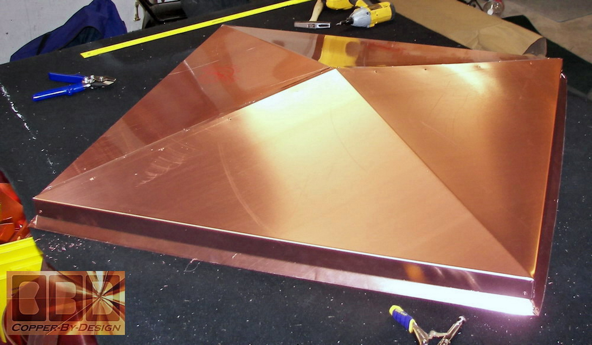
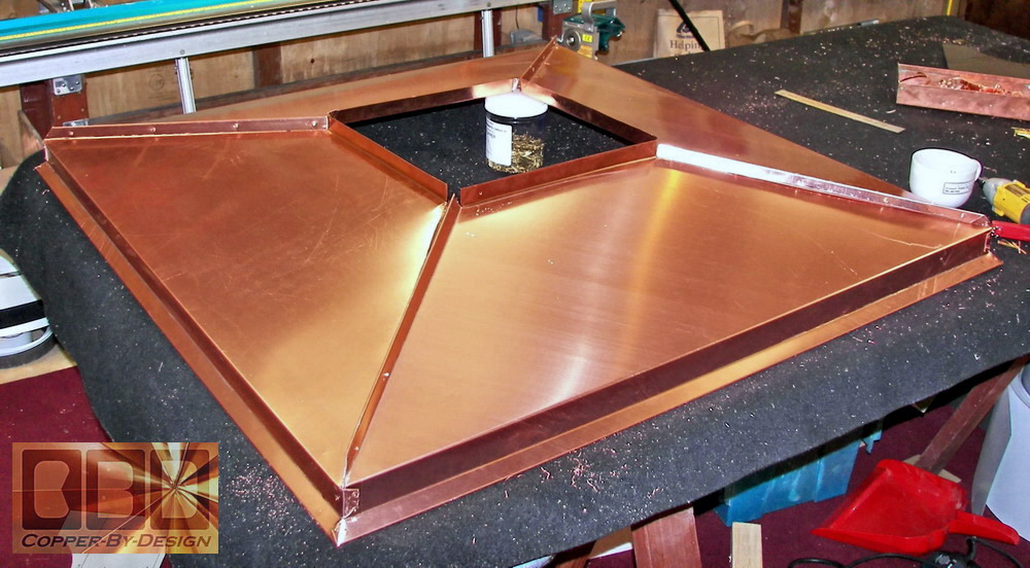
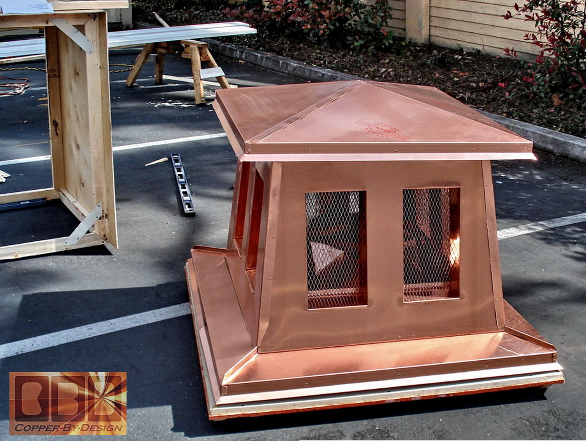
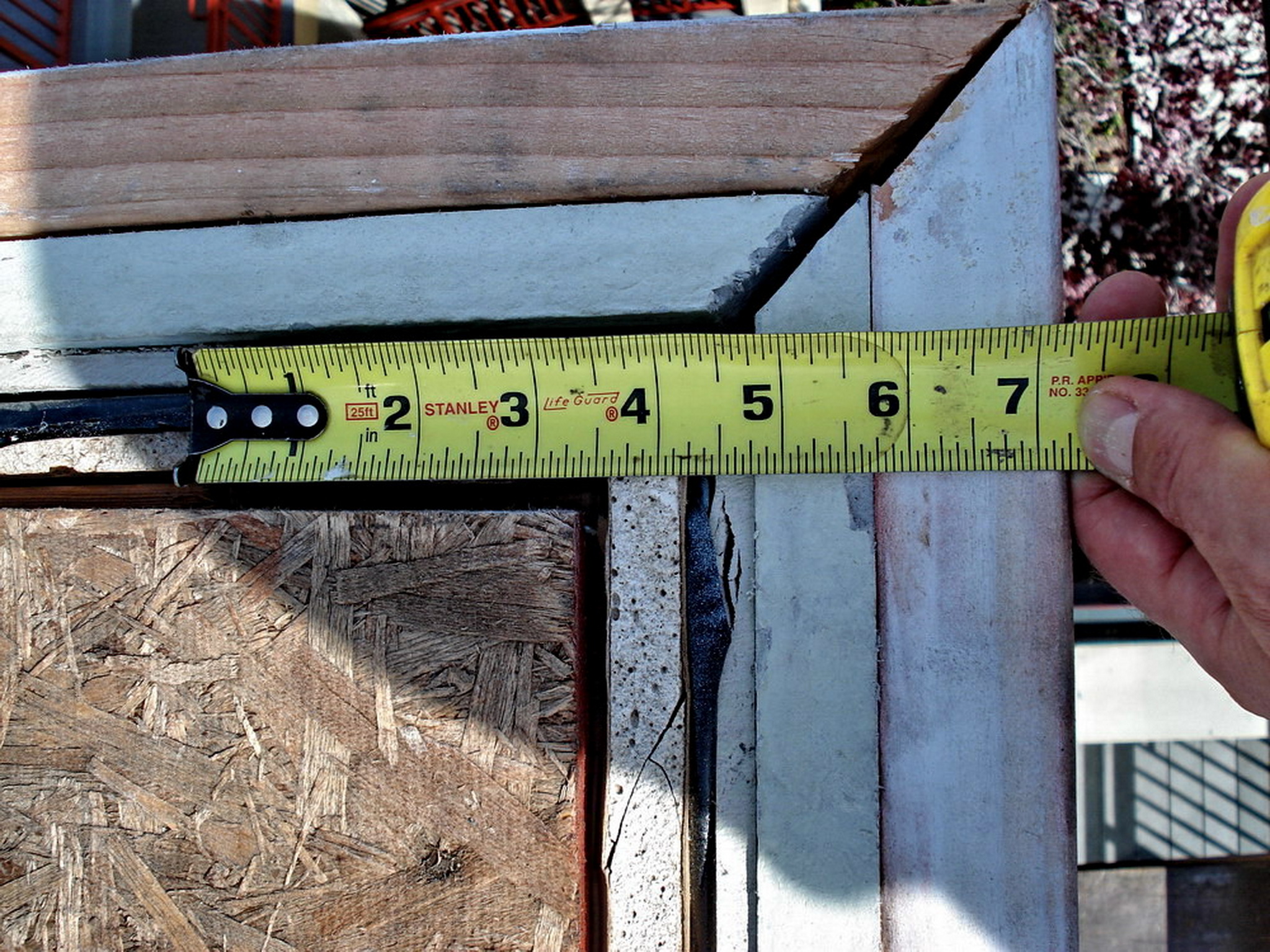
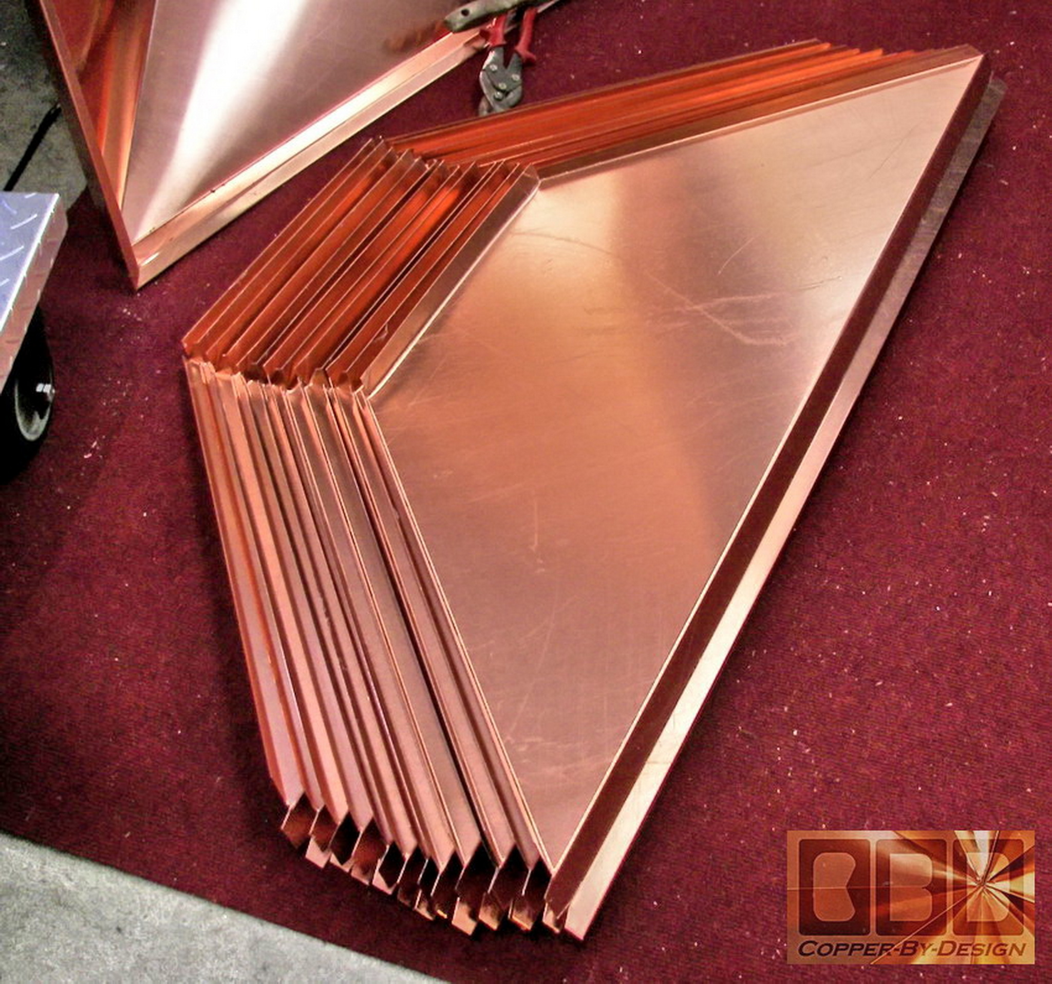
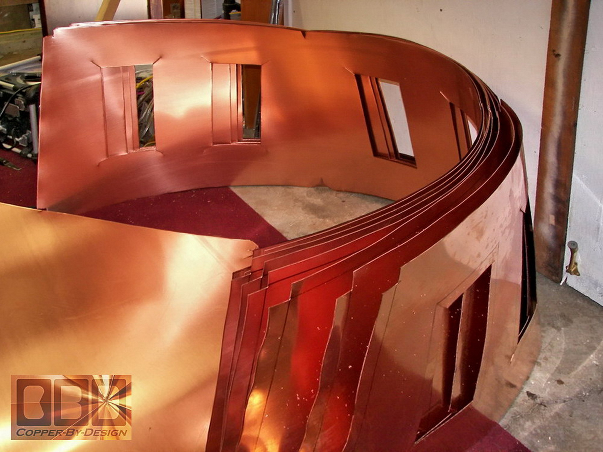
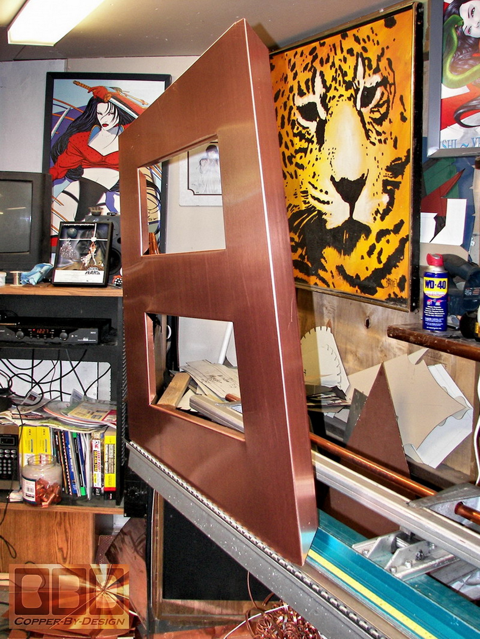
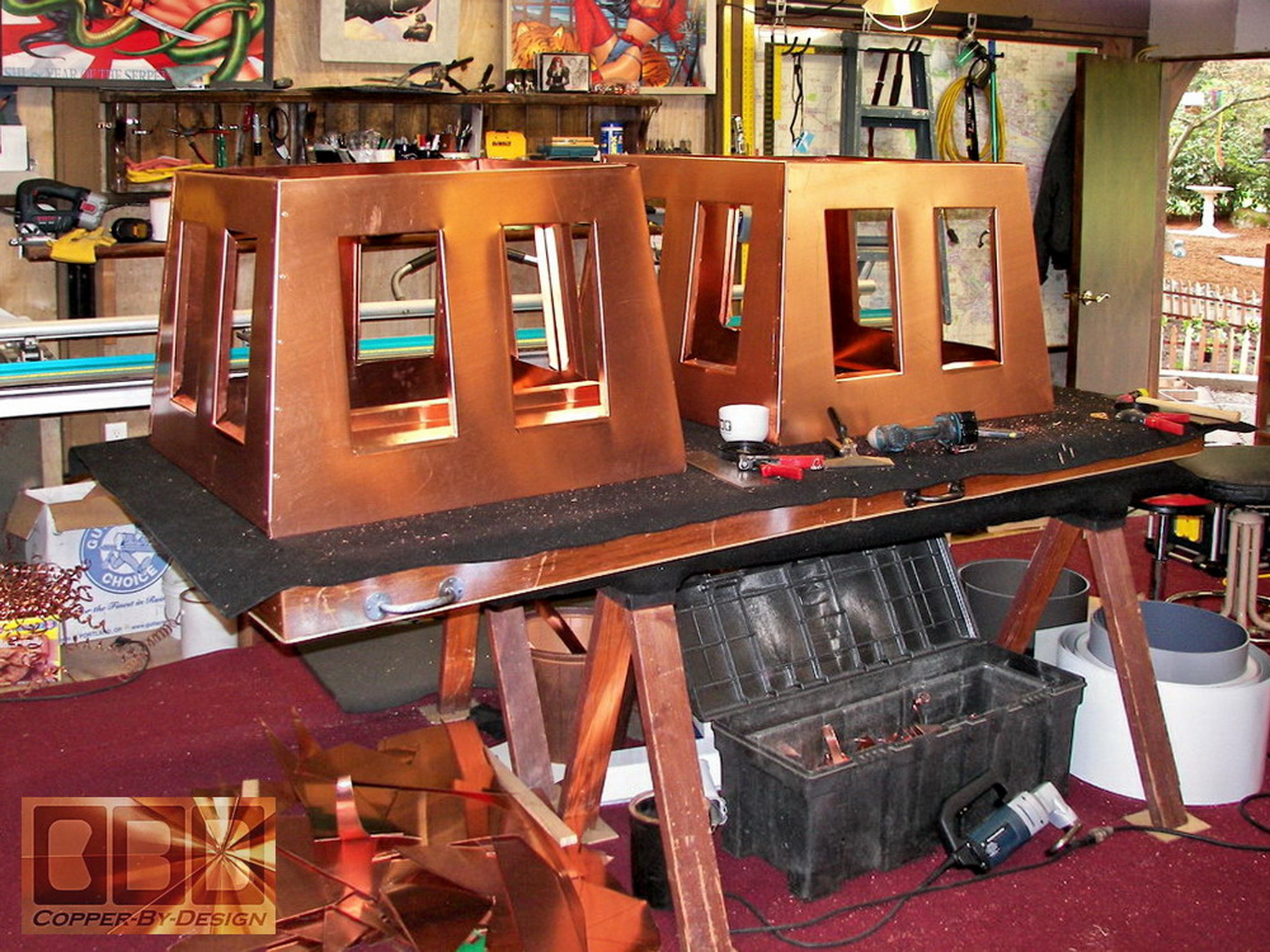
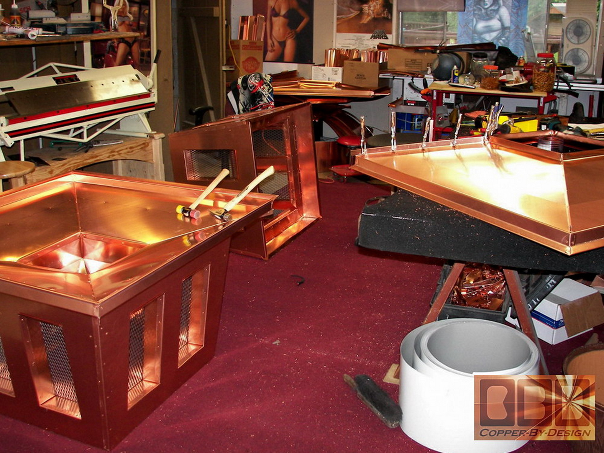
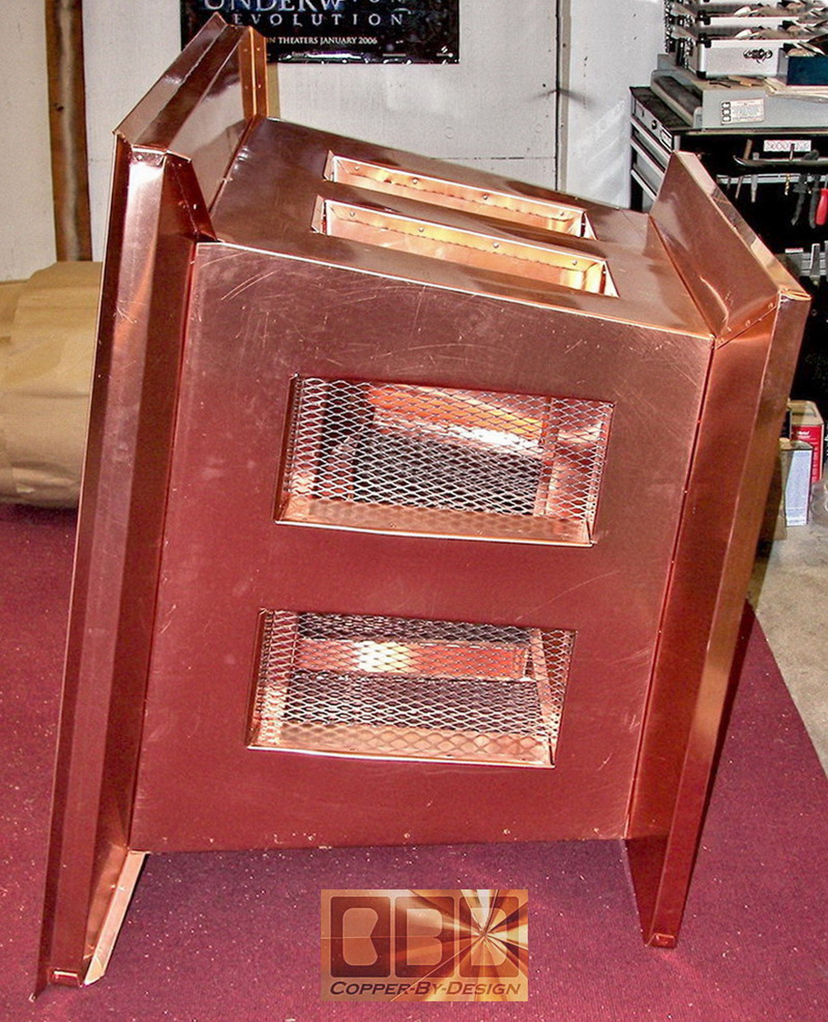
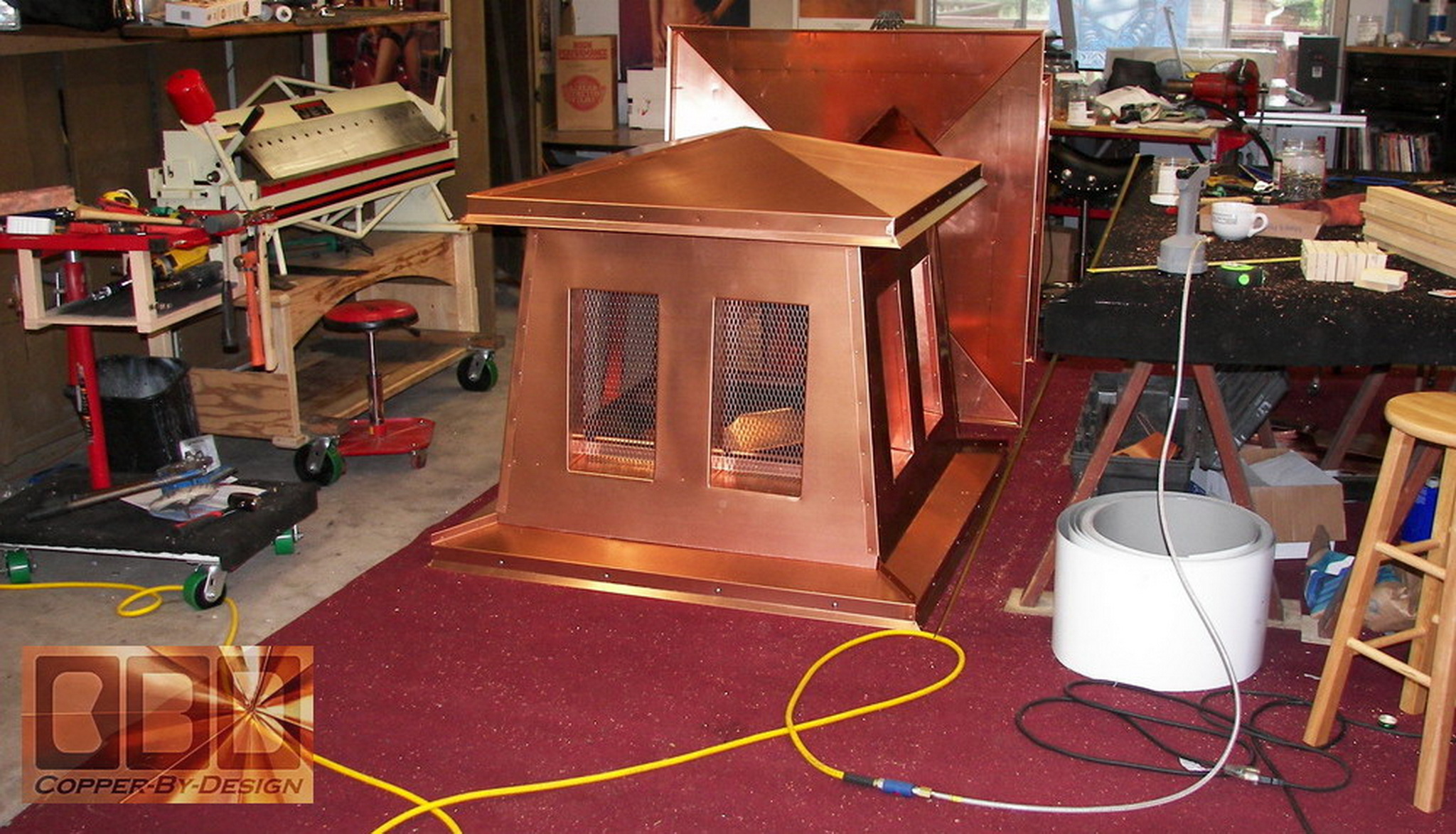
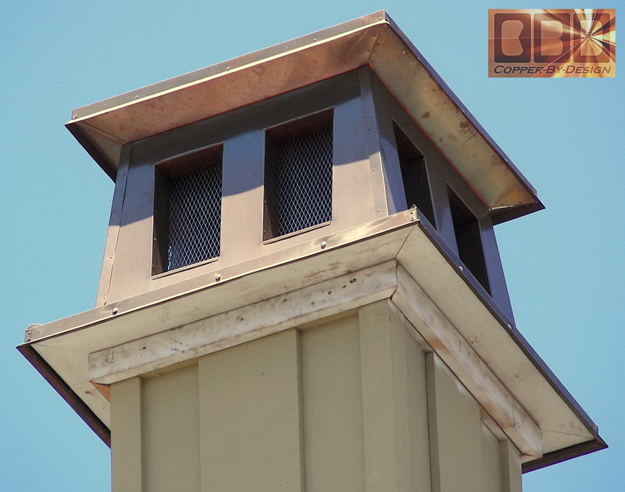
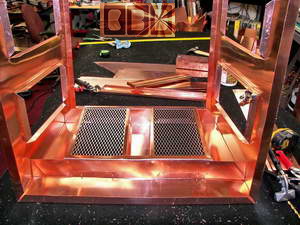
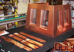
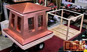
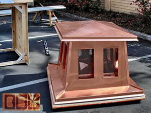
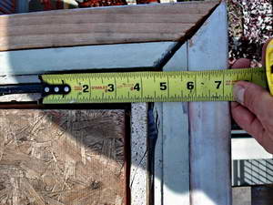
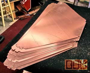
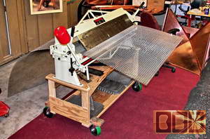
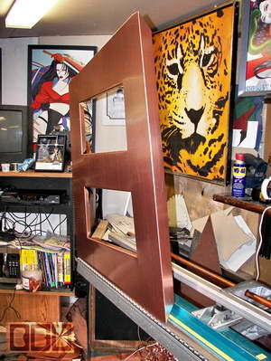
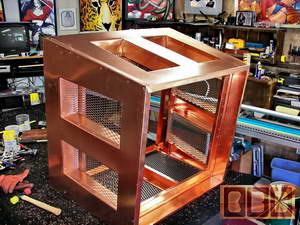
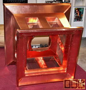
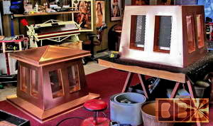
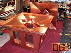
The final product design
is 46.5" wide and 37.5" high. Several inches larger than the earlier
proto-type you saw above. It took a couple days just to work out all
the details, measurements and angles to make up the templates shown
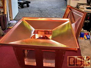
here to the left. There is a tapered pan built inside to shed rain that
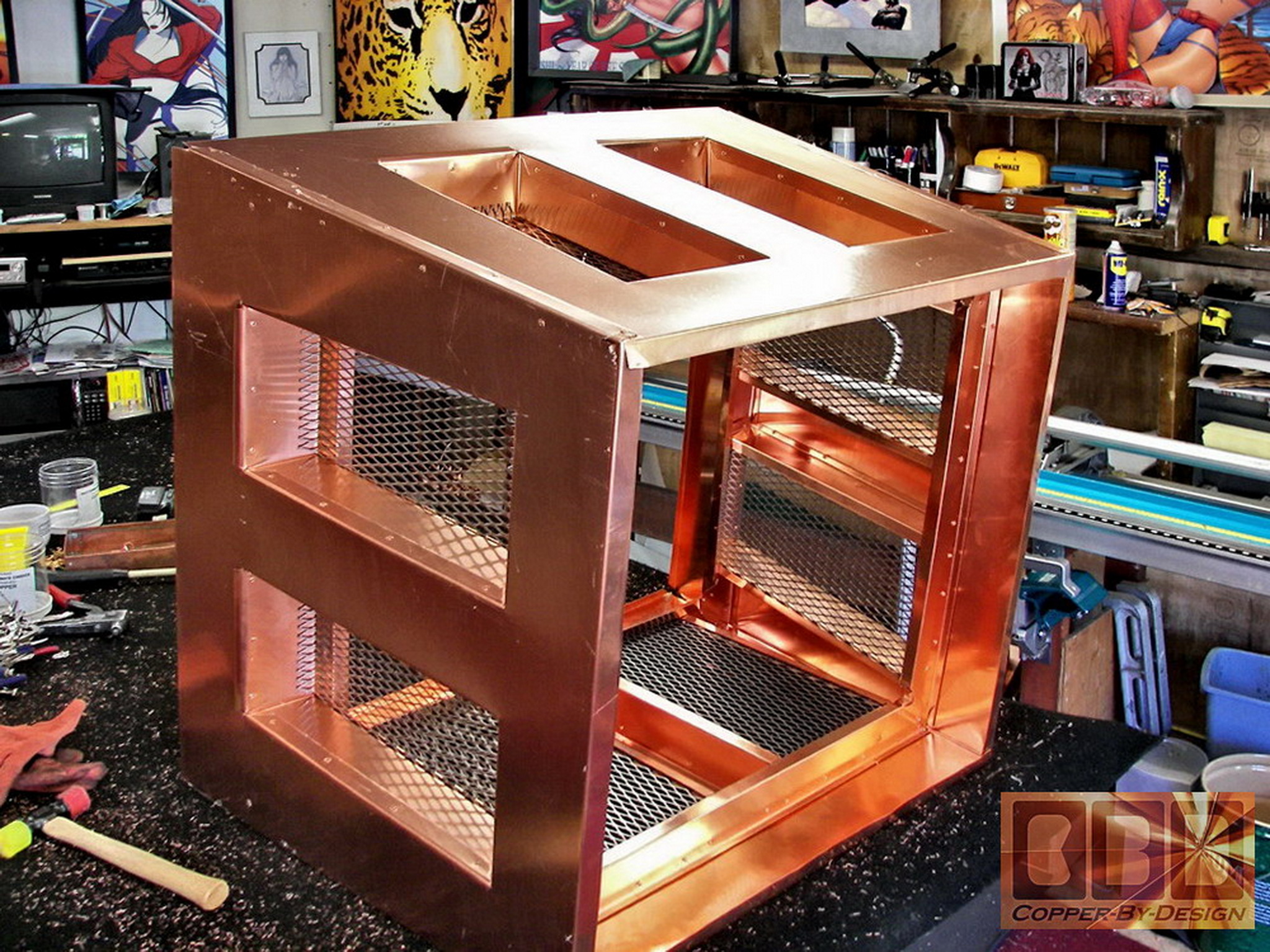
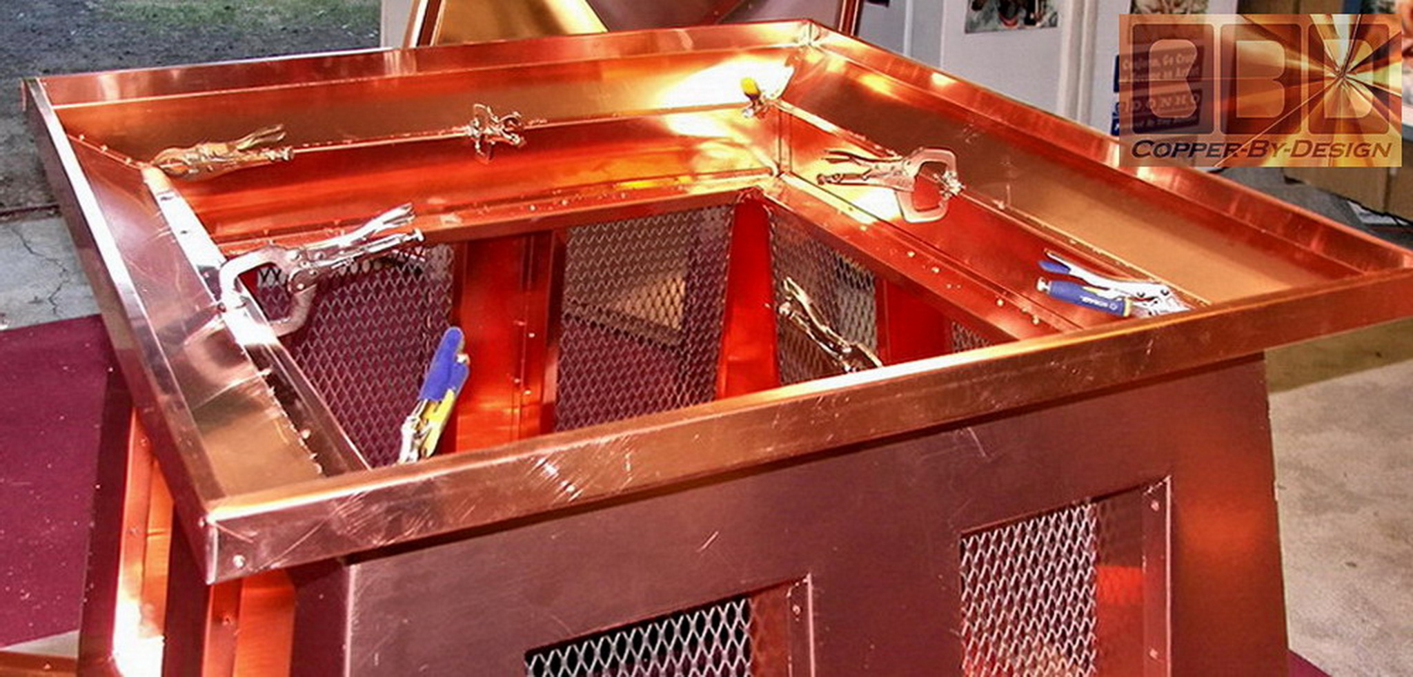
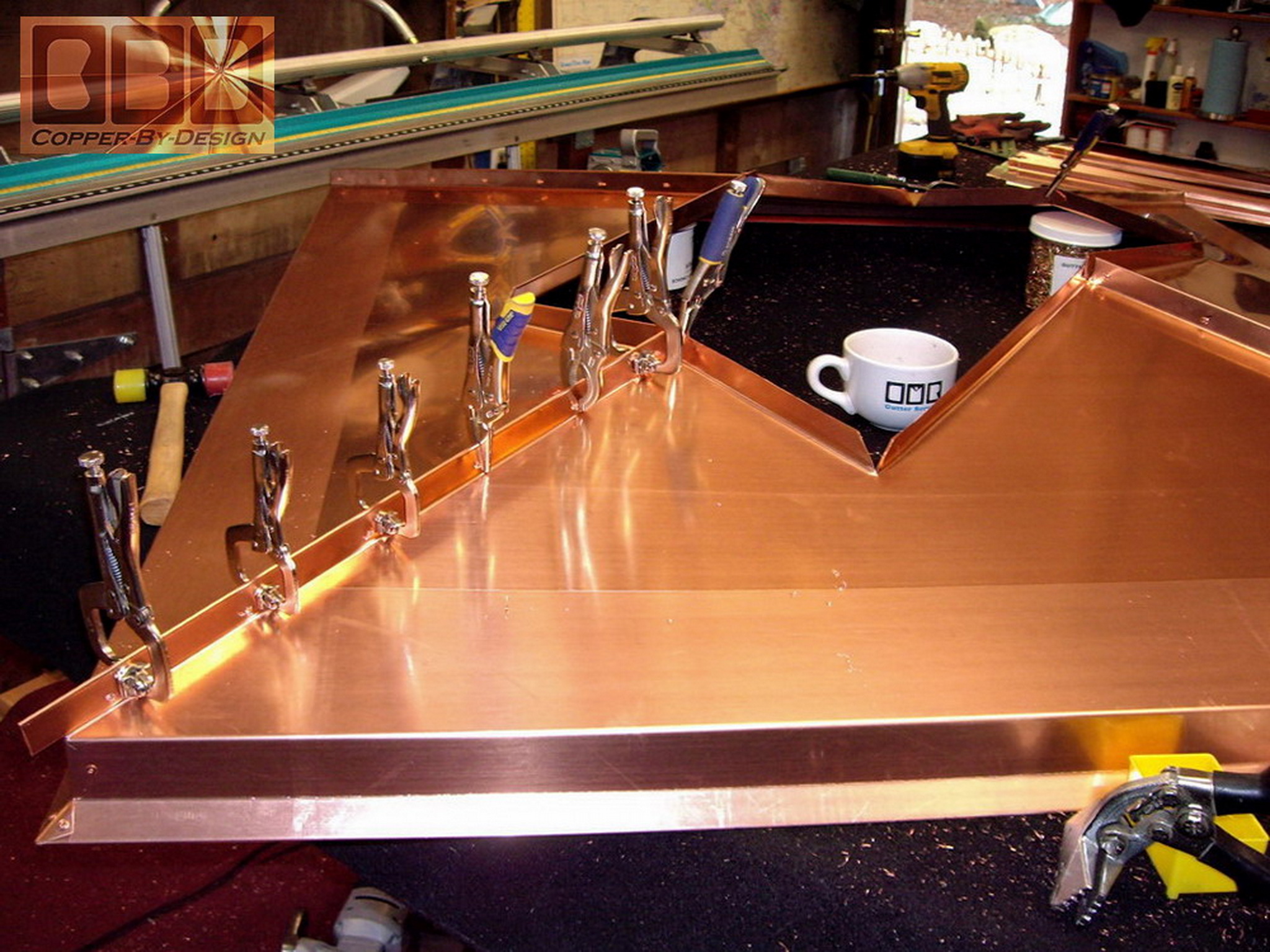
might blow in through the screened vents. The construction of
our version is shown here below in the 200 photos we took to send to
the client for their approval and to show our steady progress, since
they cannot just drive over here to see it for themselves.
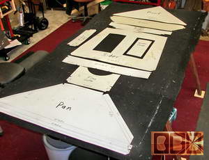 
This shows the template I made for the fabrication
of the individual parts needed. Some parts would need to be reproduced
as many as 400 times for this one order of 25 identical single flue
units. My wife Tia was willing to set her practice aside for the most
part during the 3 months this project was going to take to complete.
We even had her teen age Daughter out in the shop helping to cut and
form these parts several days. I was finally able to use up all the
copper scraps that had been piling up from previous projects.
|
|
Beginning the fabrication of the first prototype:
|
|
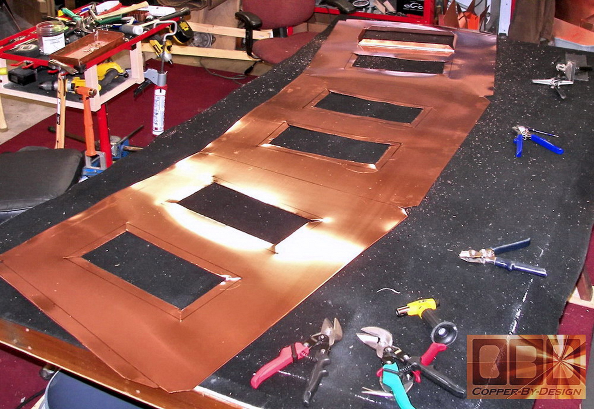
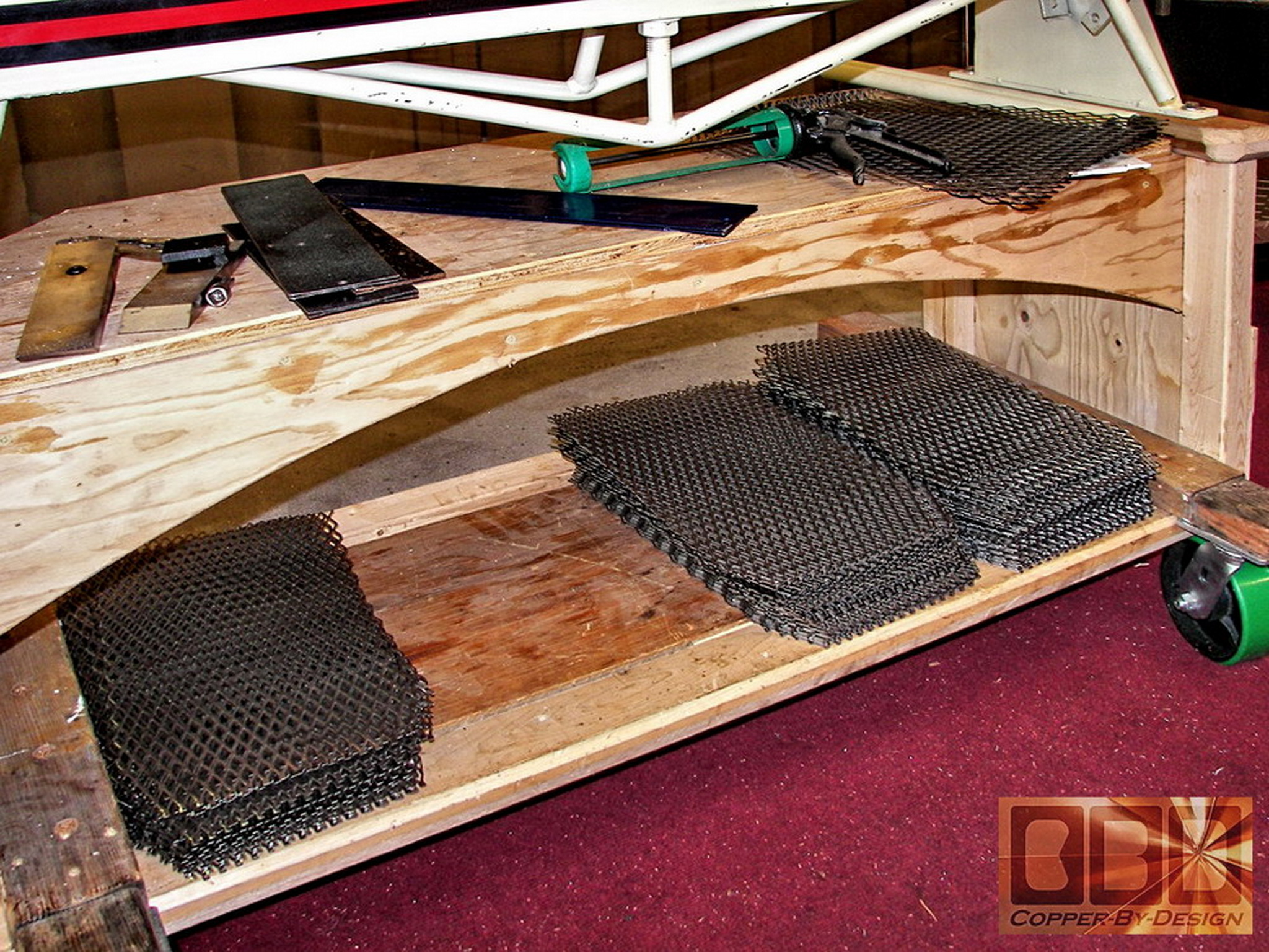
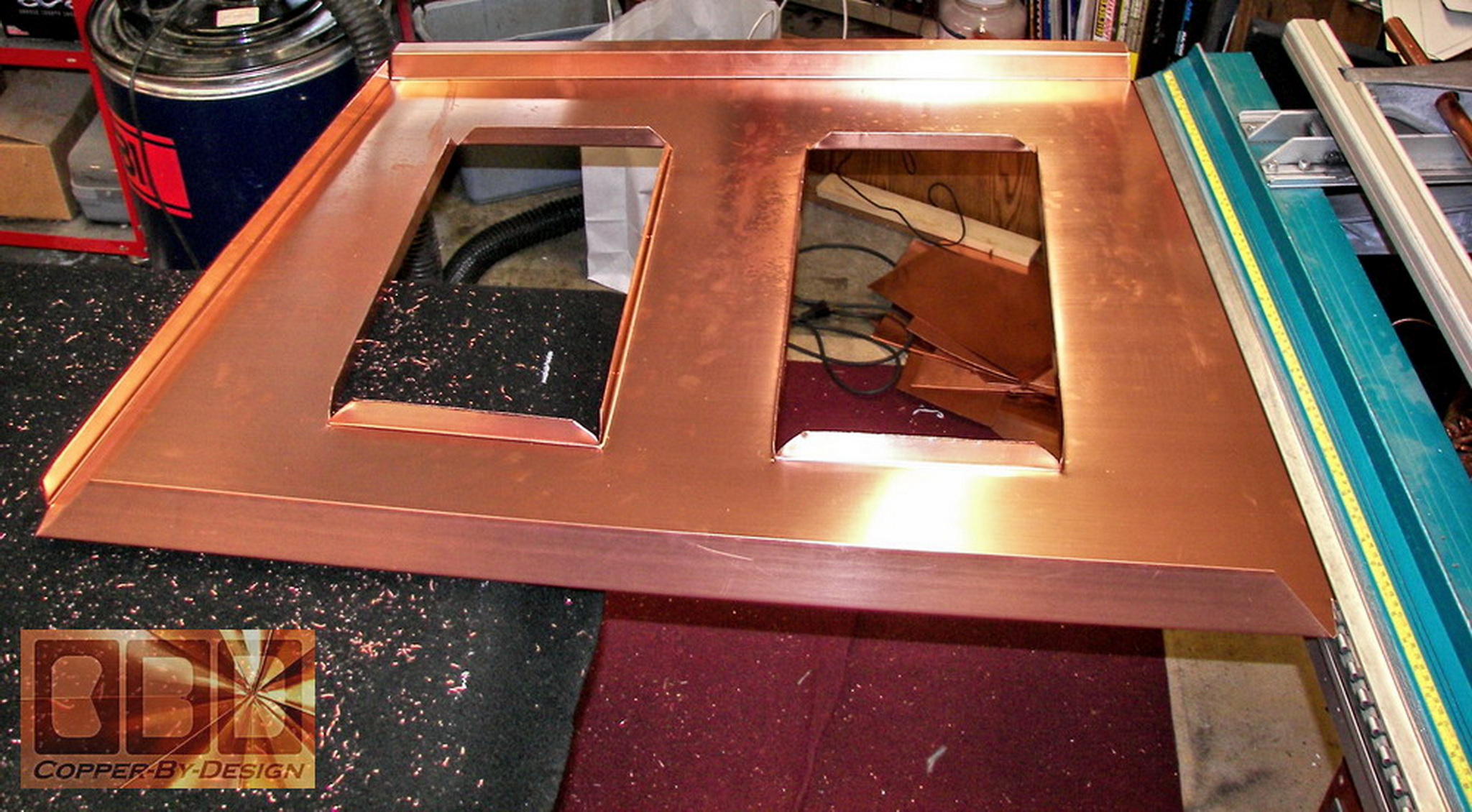
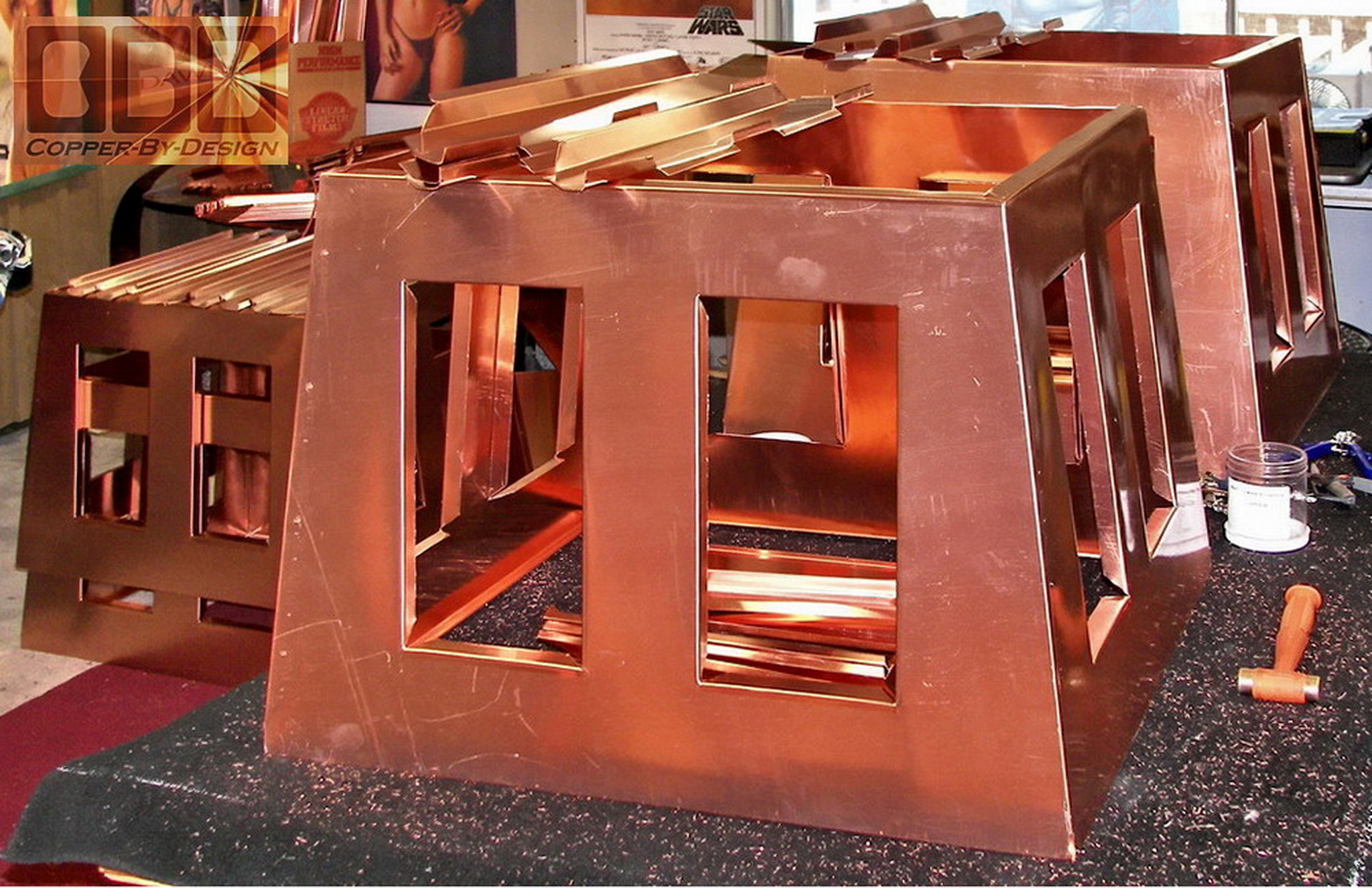
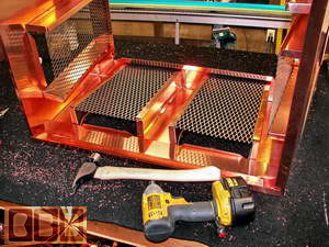
Here is the outer walls of the middle vent section
being cut out of the full 10' x 3' sheets of the 20oz copper we get.
I searched on the web for a powerful $675 Bosch electric shear that
is not sold locally to be able to cut the SS screens It also helped
with cutting these copper sheets quite a bit, but the shear was very
heavy at over 10lb.
I managed to make these 3 out of 4 sides all in
a single piece, so it was as seamless as possible. I had to use a large
hole saw to make an opening in each vent to get my tin snips in to cut
out the center by hand. That was 224 vent holes in all I needed to cut
out. Between this and the 500 rivets each unit took, I was literally
working my wrists into carpal tunnel and loosing circulation in my hands.
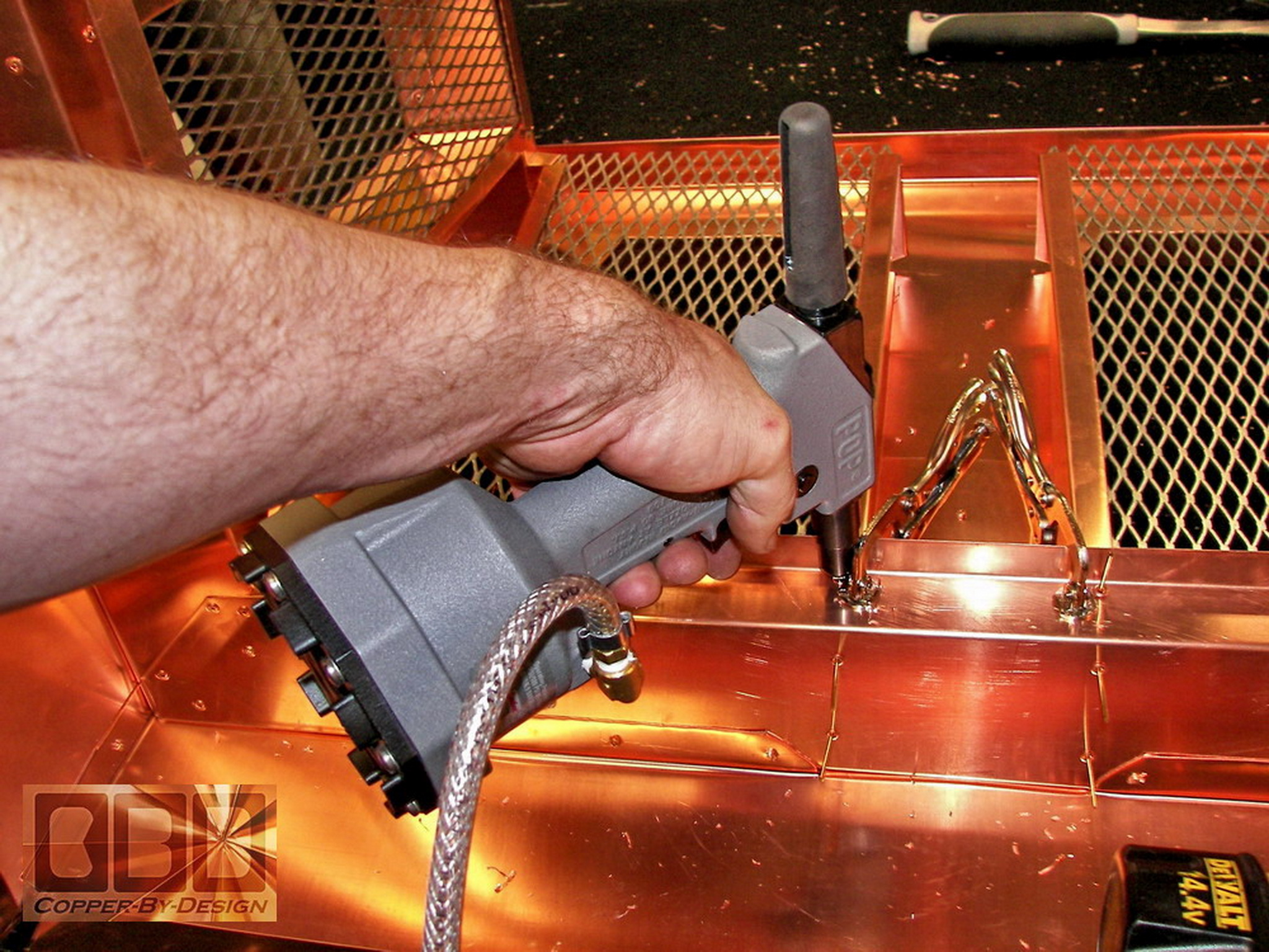
About half way into this project I finally broke down and sent for a
professional pneumatic riveter to help relieve this condition.
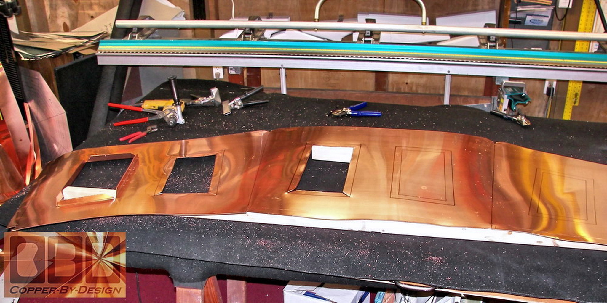
I bent the inside flanges for the rectangular
vents to attach the inner 3" deep set framework that will go inside.
This helps stabilize this section to better work with it. It is tricky
to work with such a large 9' long sheet of copper and get all these
34 bends in just the right order without getting this sheet all tweaked
out of shape first. It took the two of us to carefully handle these
large sections.
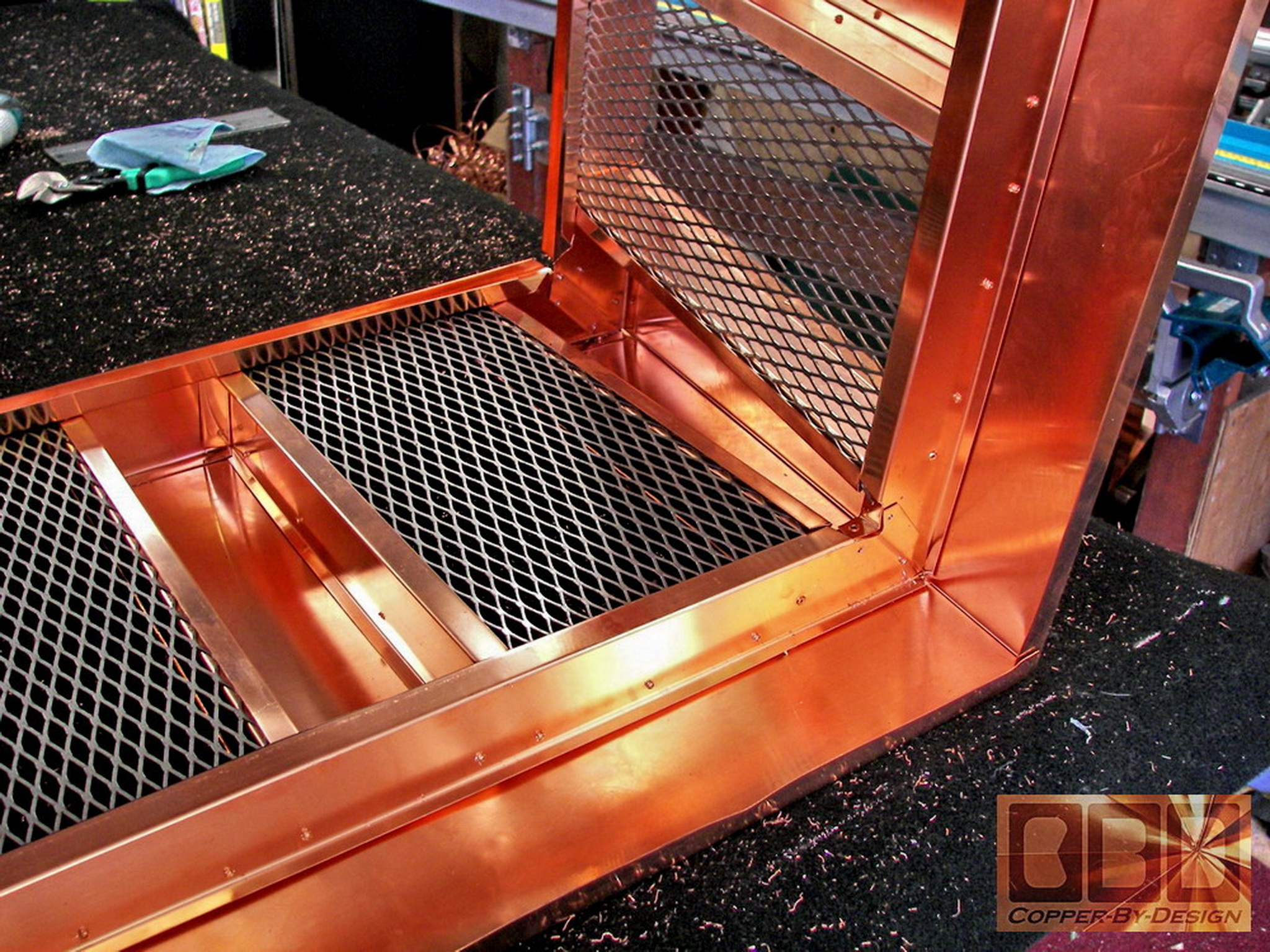
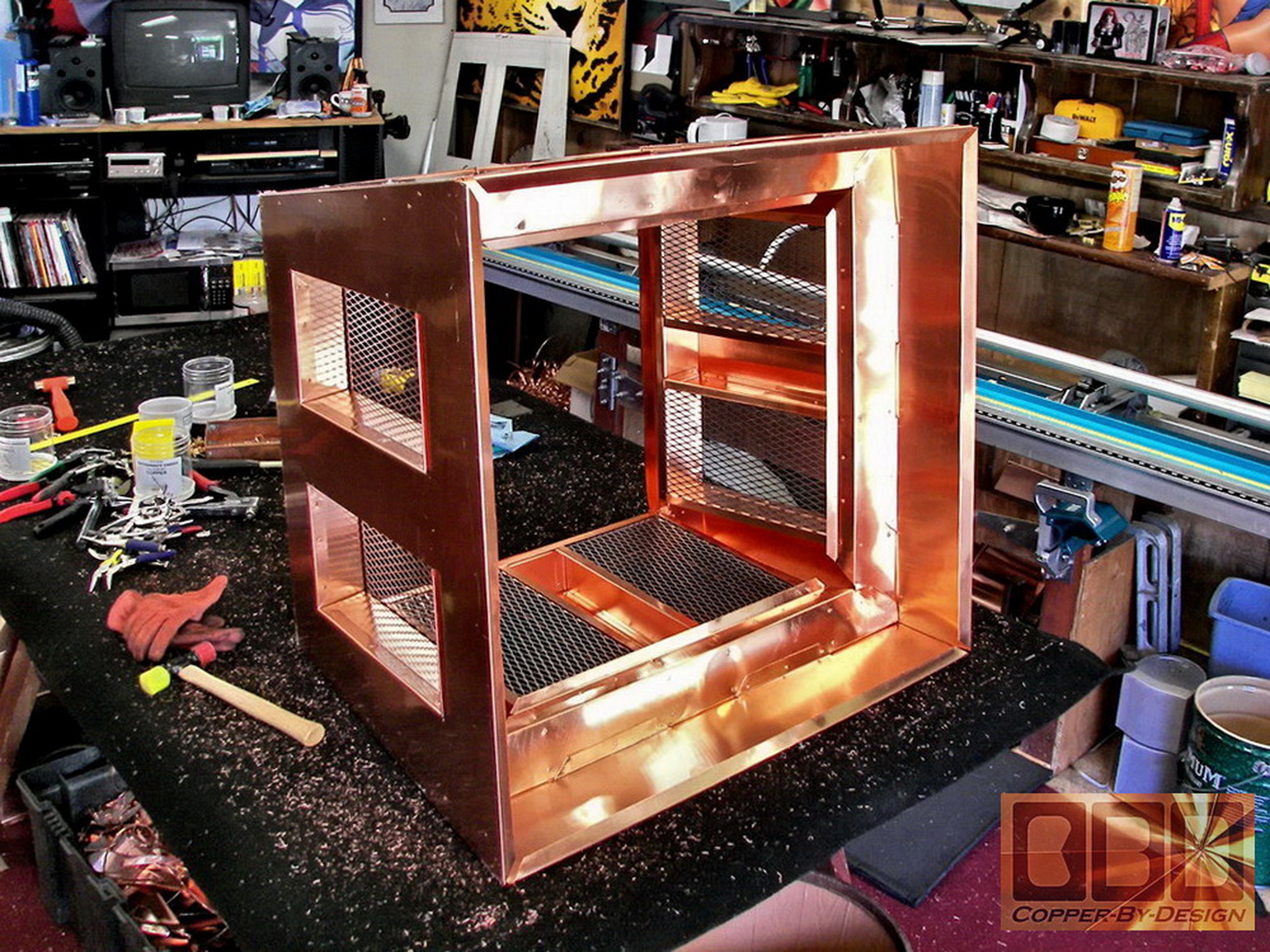
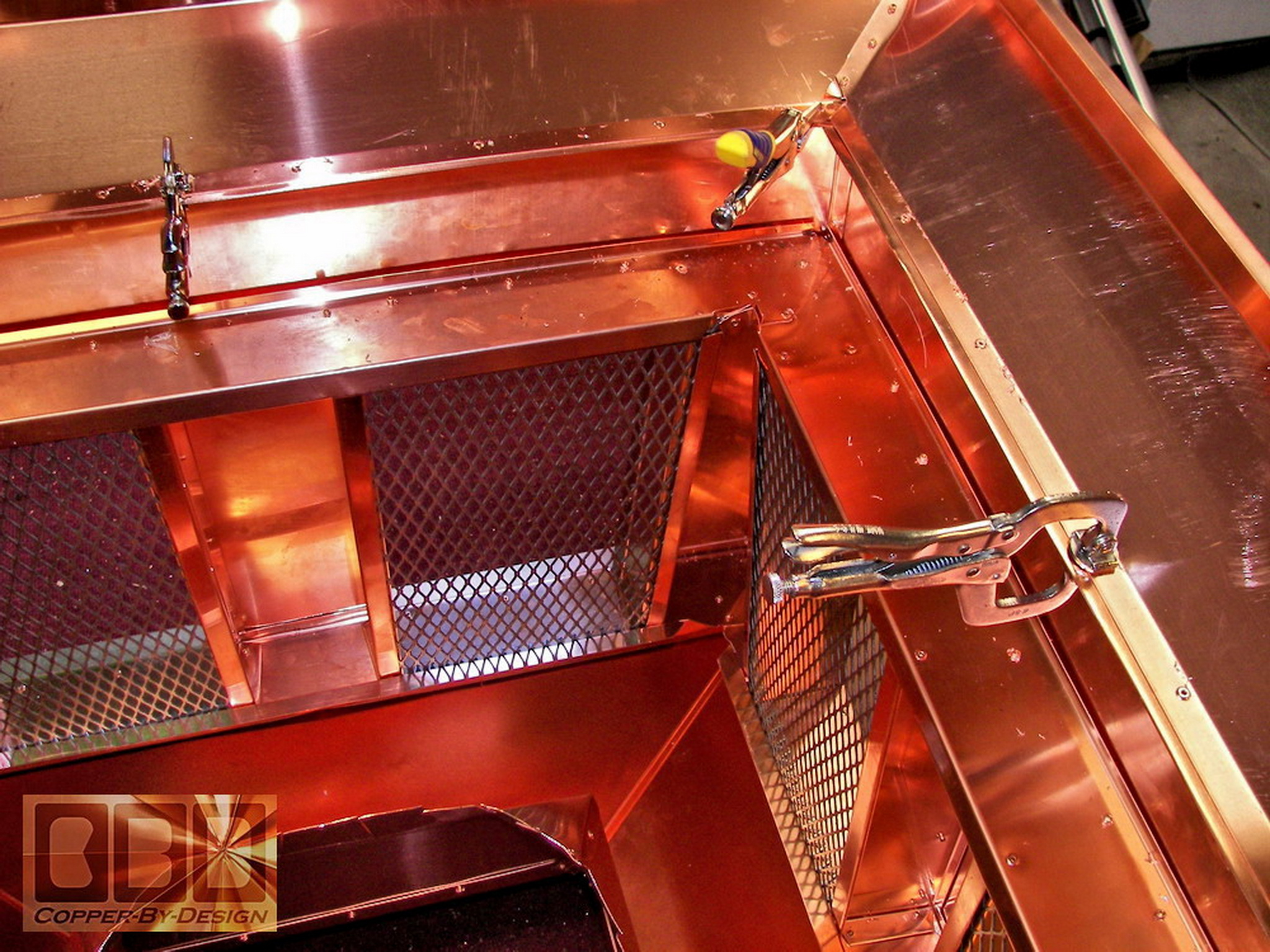
This shows attaching the inner framework to the
outer walls and inserting the stainless steel screen material in the
vent opening. It had to be held securely in place in these copper channels
we fabricated in these pieces.
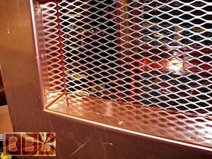 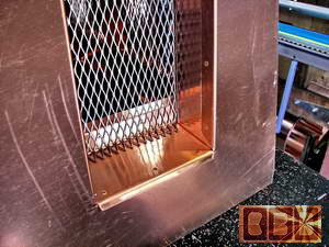
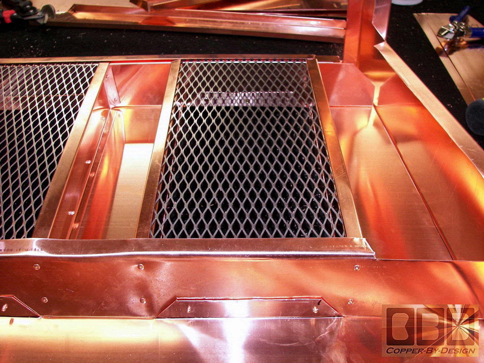
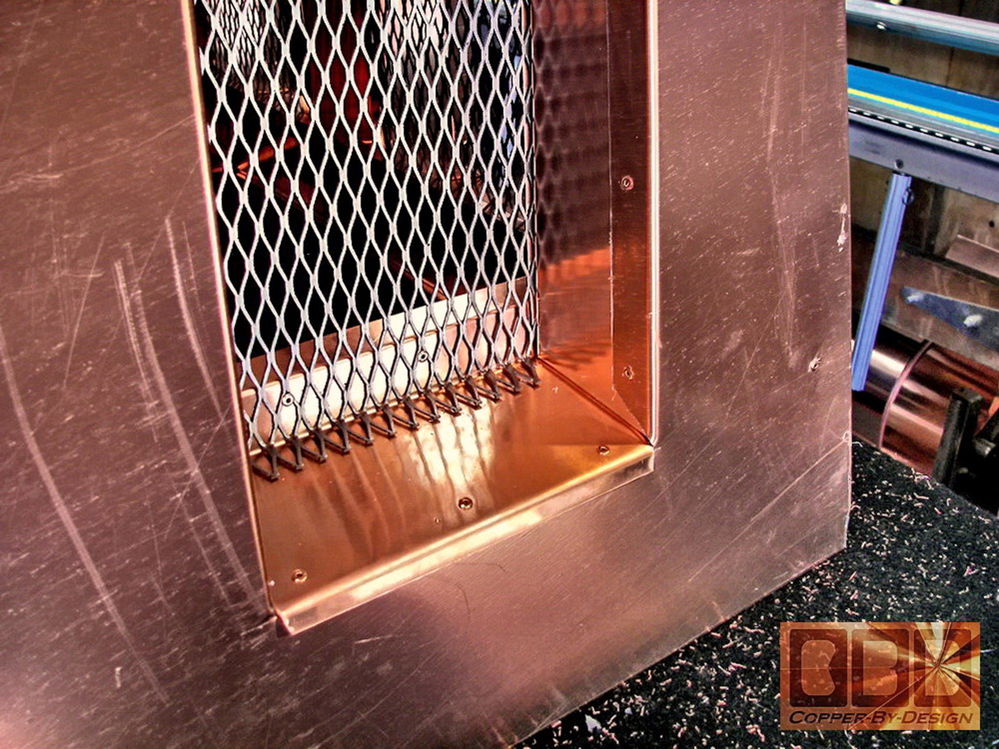
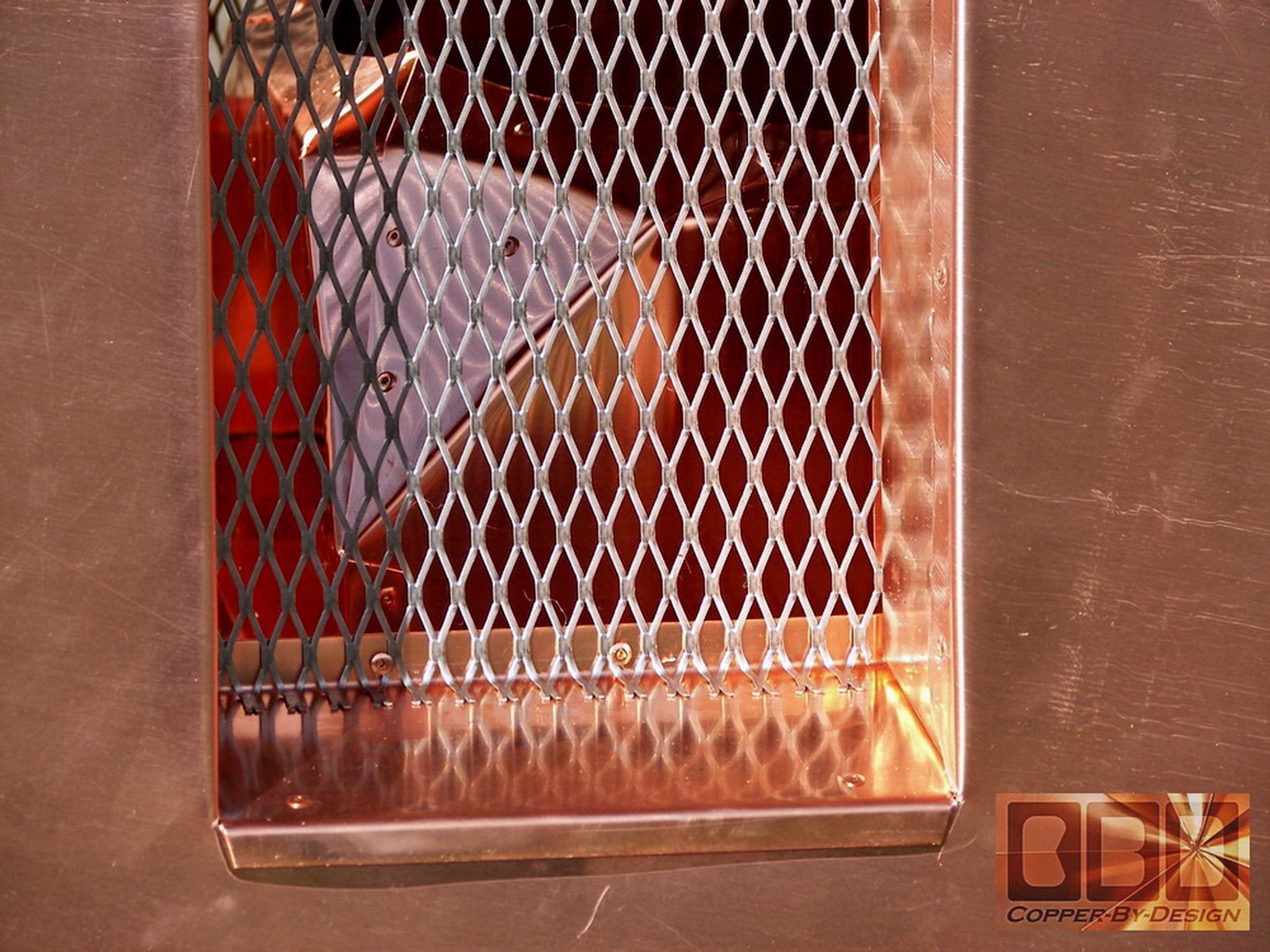
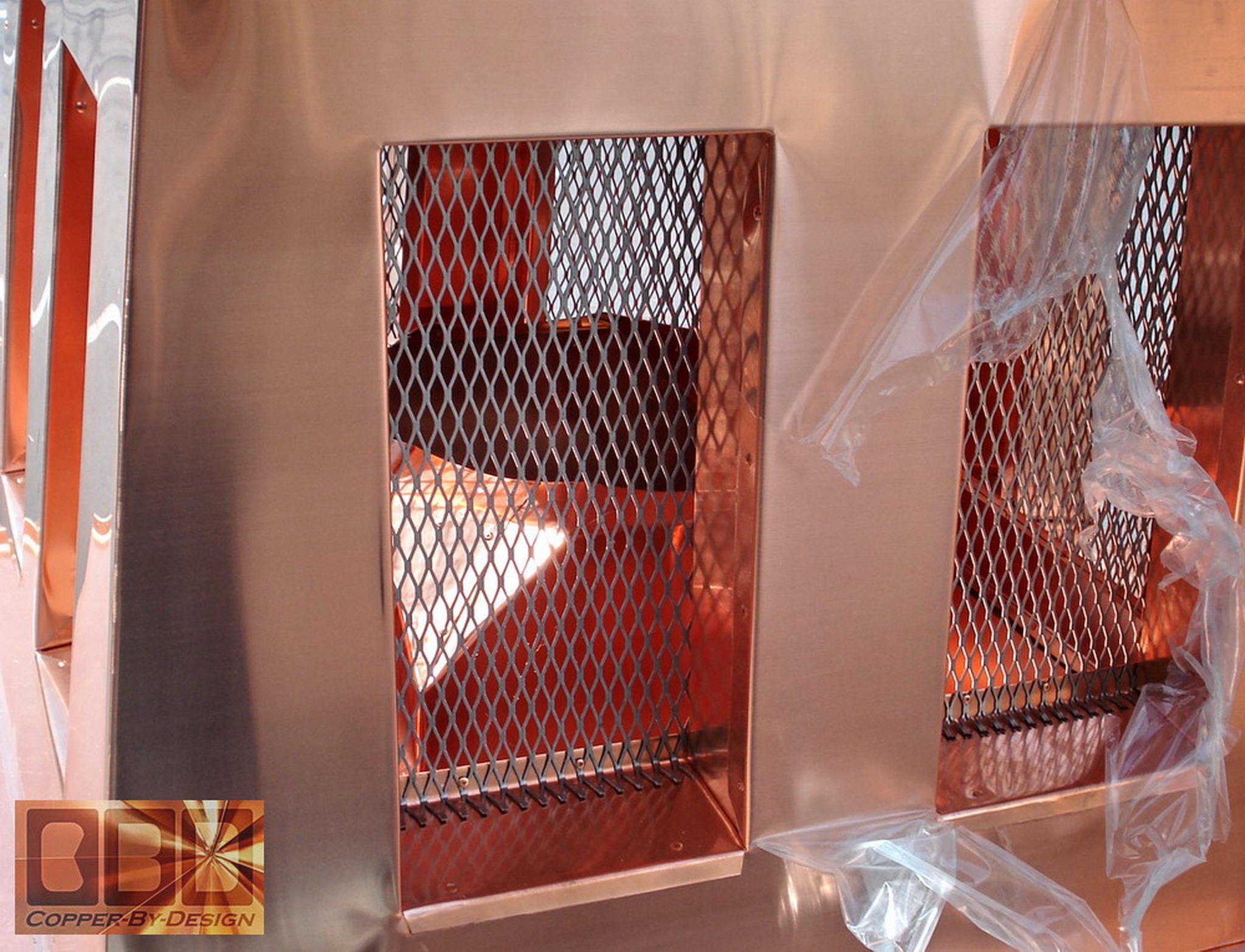
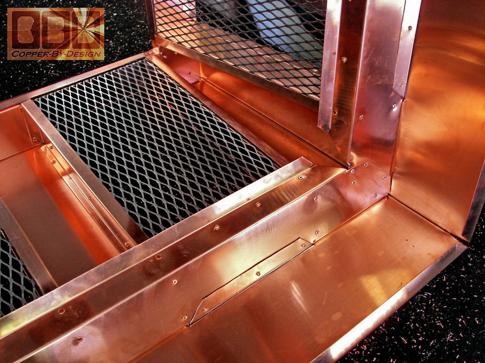
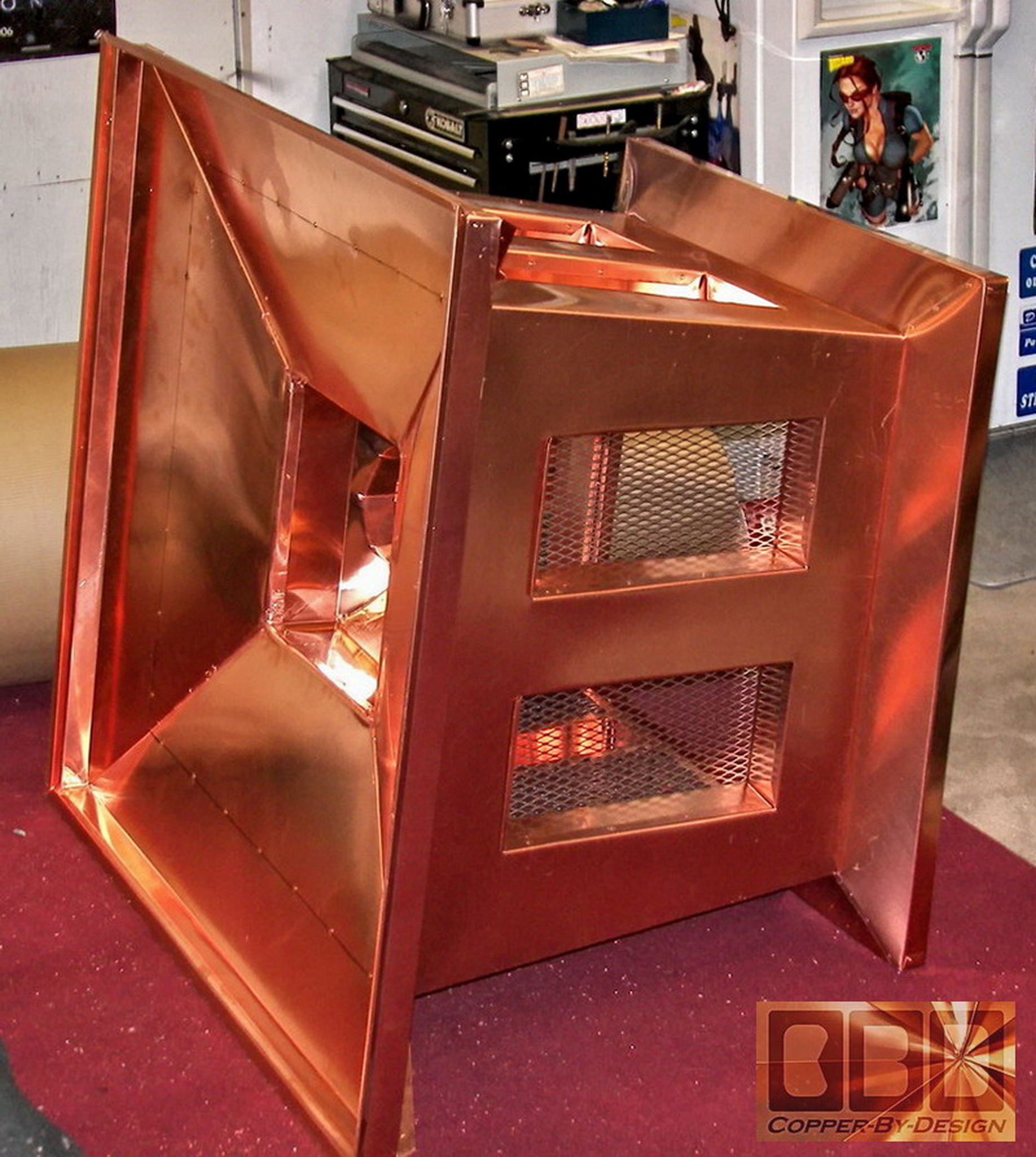
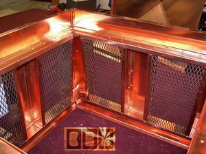
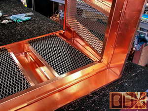
We went out of our way to design these to minimize
the visible rivets and hide the transitions from the outside. The first
photo on the left shows the top of the vent frame from the outside laying
on it's side. In the second photo on the right shows how I designed
it so when the wind blows rain water under the roof onto these screens;
the bottom of the screens will be able to drain off that water over
this vent pan that will shed the water outside the walls of this mid-section.
Also that screen is bent out at the bottom to add strength and to avoid
sharp edges that could scratch and dig holes in the copper over time
throughout the next century.
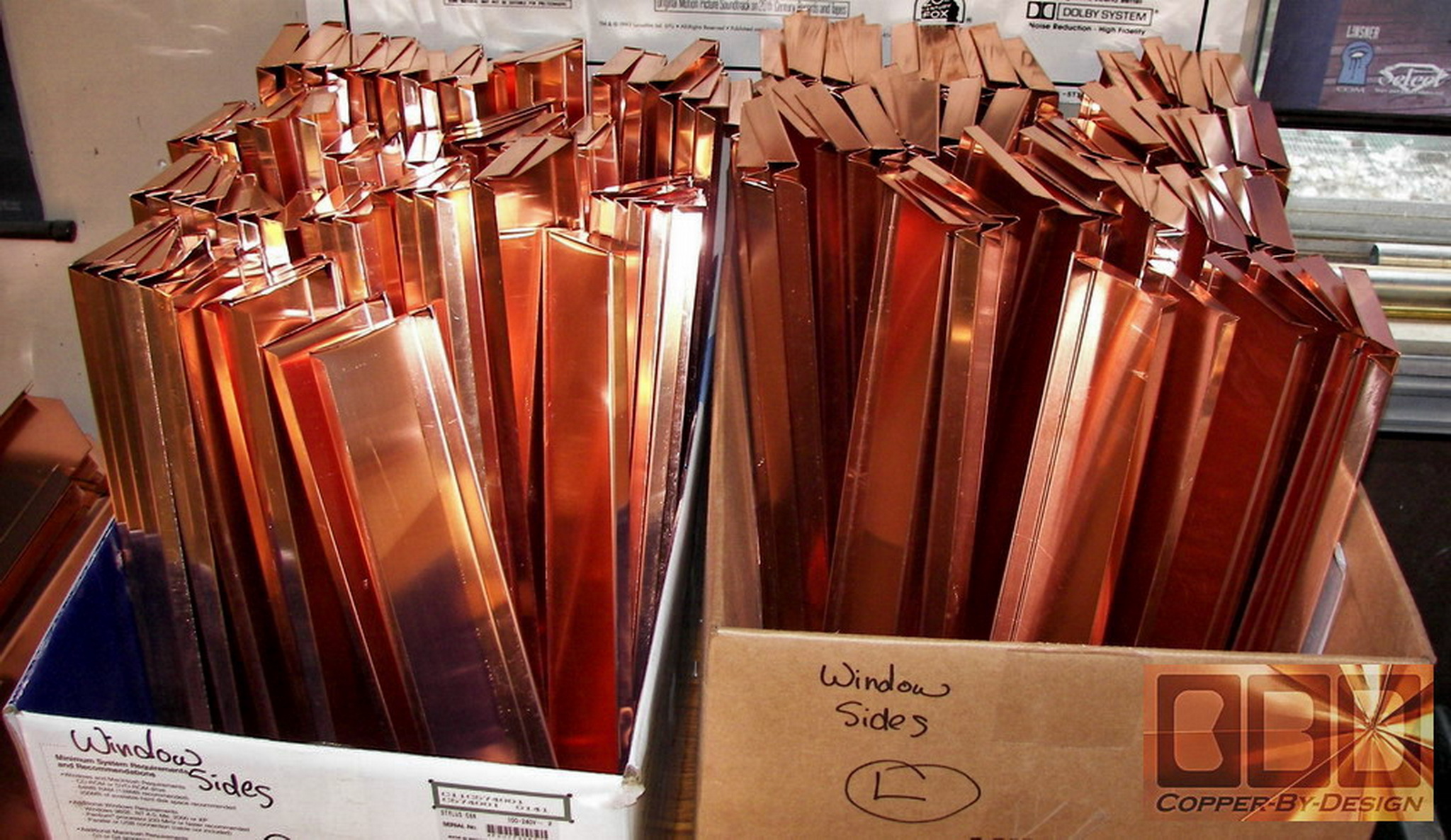
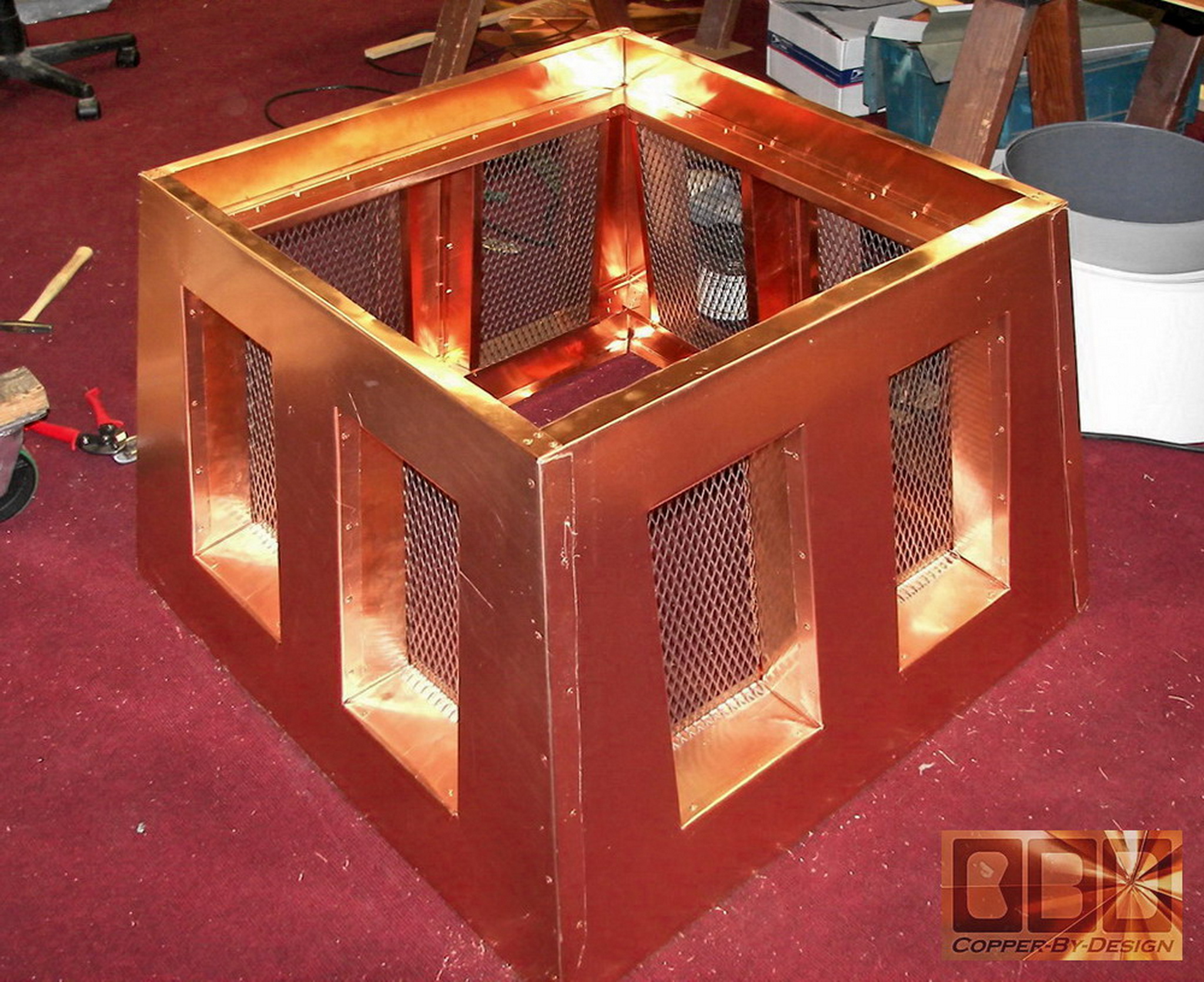
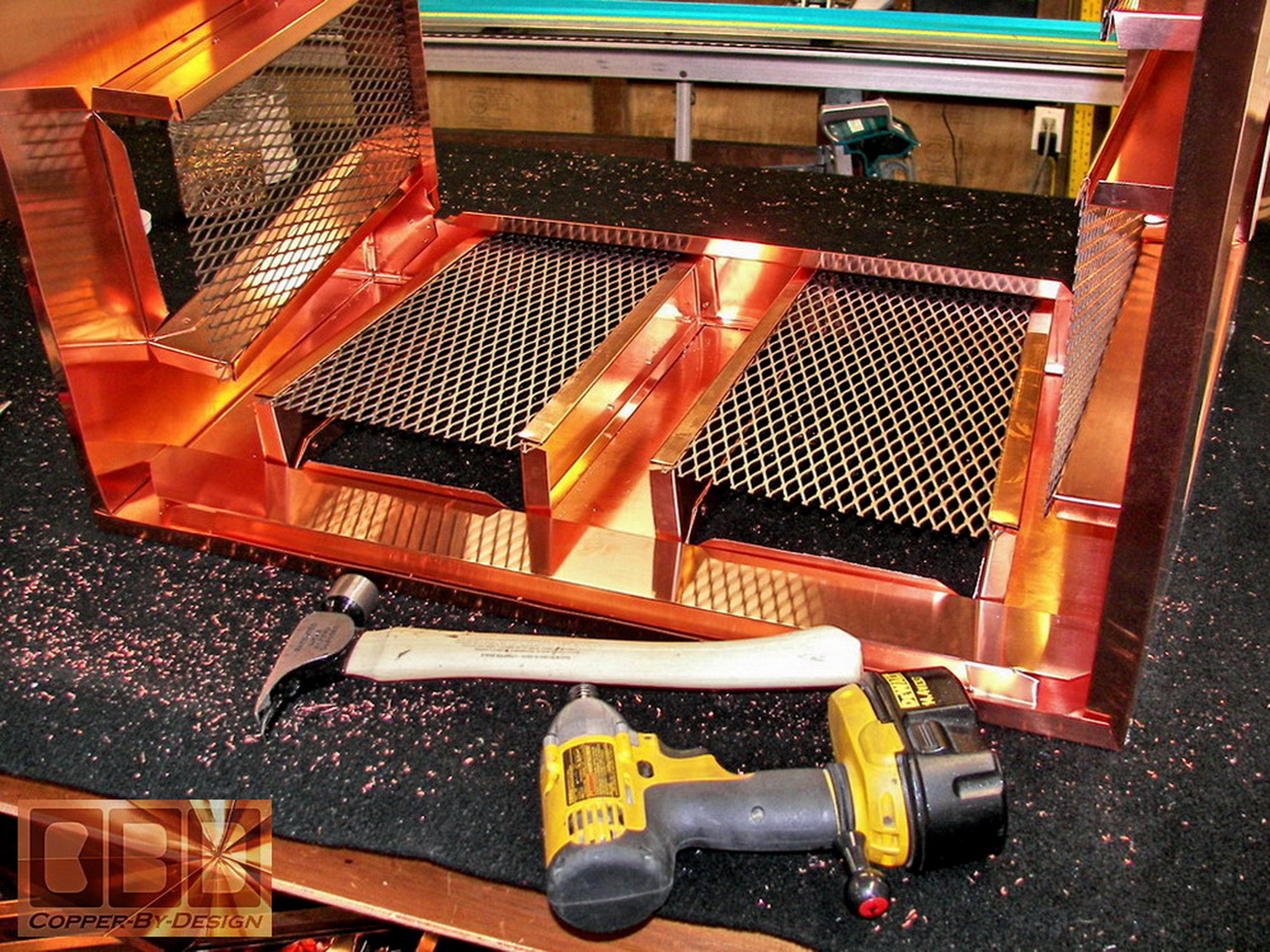
Each chimney cap would need 16 vertical side pieces
with 4 top and 4 bottom horizontal cross pieces that would span the
width of this section just inside the outer walls you see here. then
all riveted in place at just the right angles to also shed the rain
water to the outside of the outer walls. The ends of the horizontal
pieces are riveted together inside the corners to add that much more
strength to this section than it would have had without this deep-set
screen design.
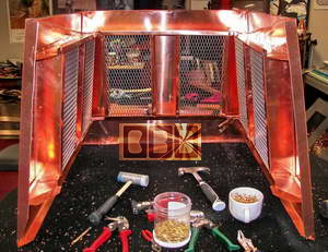 
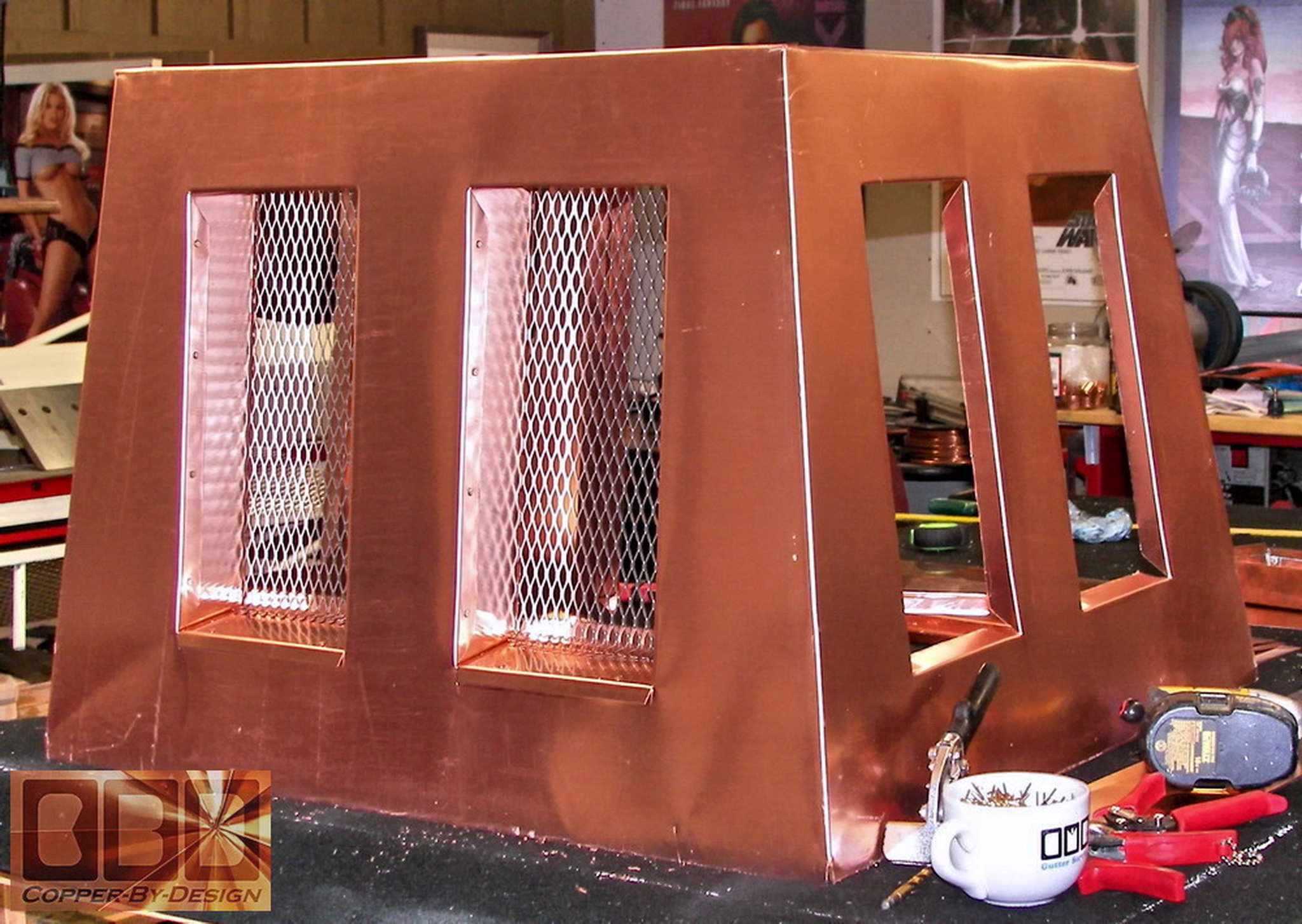
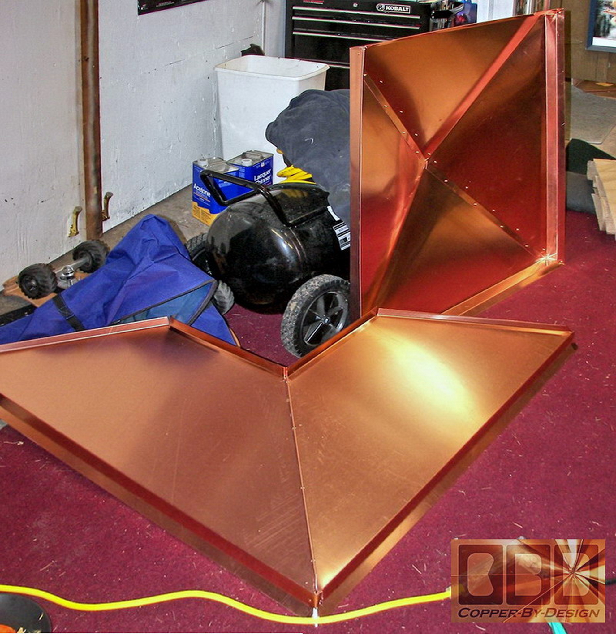
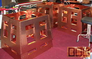
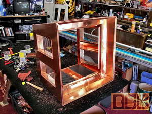
More rigidity will be added when it is attached
to the pan base, but after the 4th side was on and riveted together
and I lifted it up to move it down to the floor, it had very little
flex to it. It was amazing how much strength these added to this center
section. It is nice to know how strong these units will be, just starting
out from some thin flat flimsy copper sheet metal.
The second photo shows it laying on it's side
with the eave section attached to the top of the mid vent section
|
|
Building the roof section:
|
|
This shows the 2 part roof section being riveted
together. I tried to encourage them to go with a bit steeper pitch to
add strength to this hipped rood, but they were resistant to abandon
the flat top look they had originally designed.

I feel from a design stand point that it is best
to match the roof pitch of the house, so the chimney cap looks like
it was meant to be on that house from the original architect designs
(like shown in this drawing), but some times you just need to know when
to let go and have the client decide what is best.
|
|
Attaching the roof and pan section:
|
|
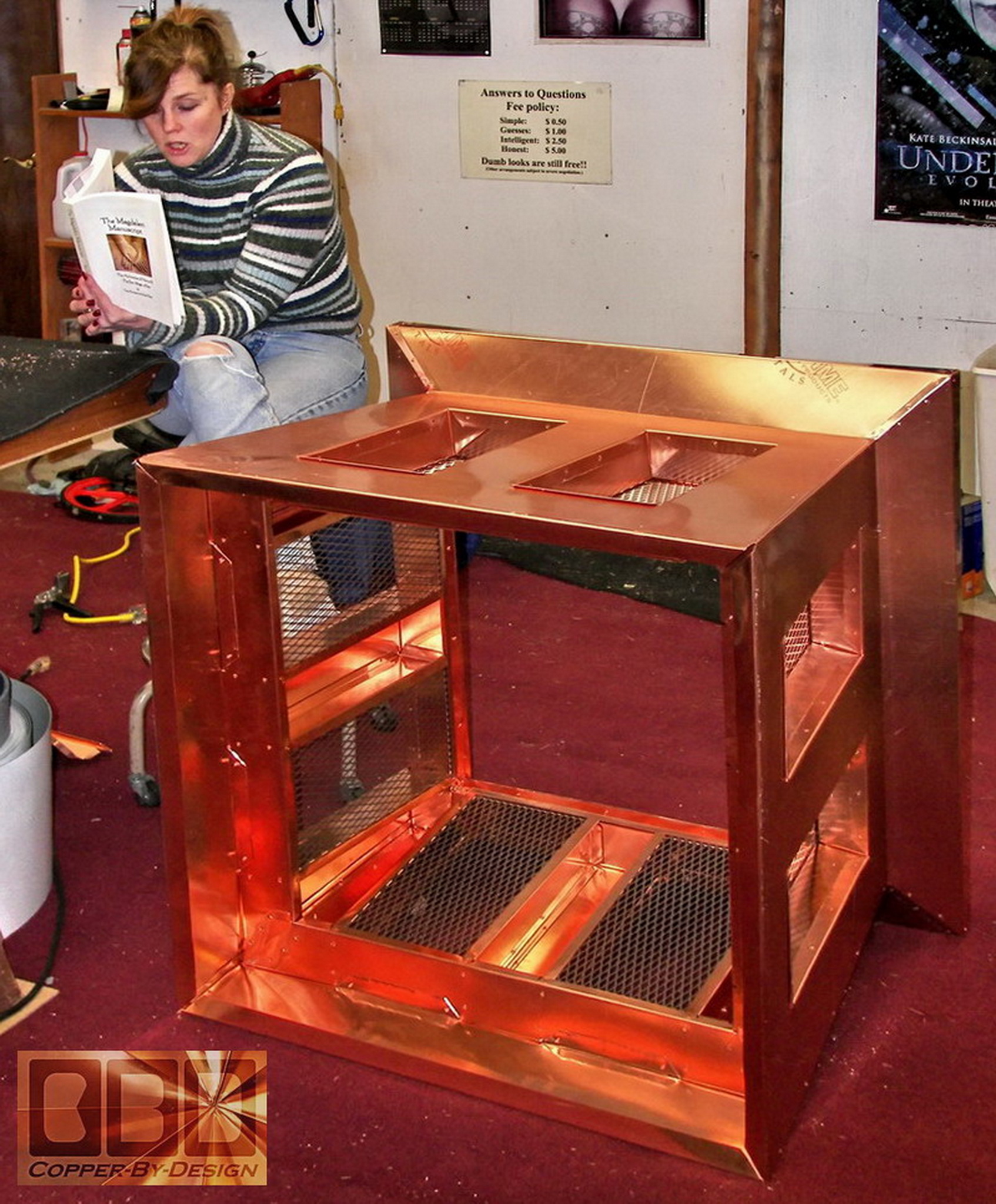
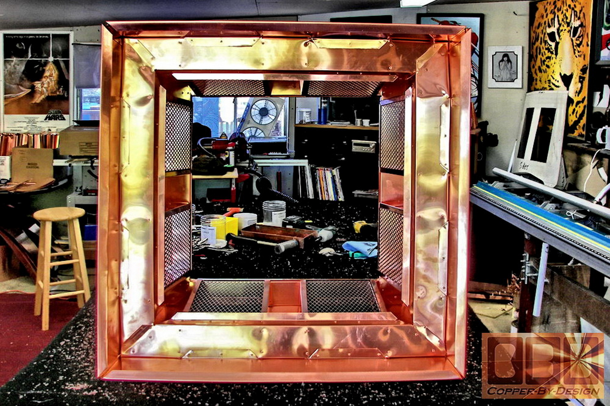
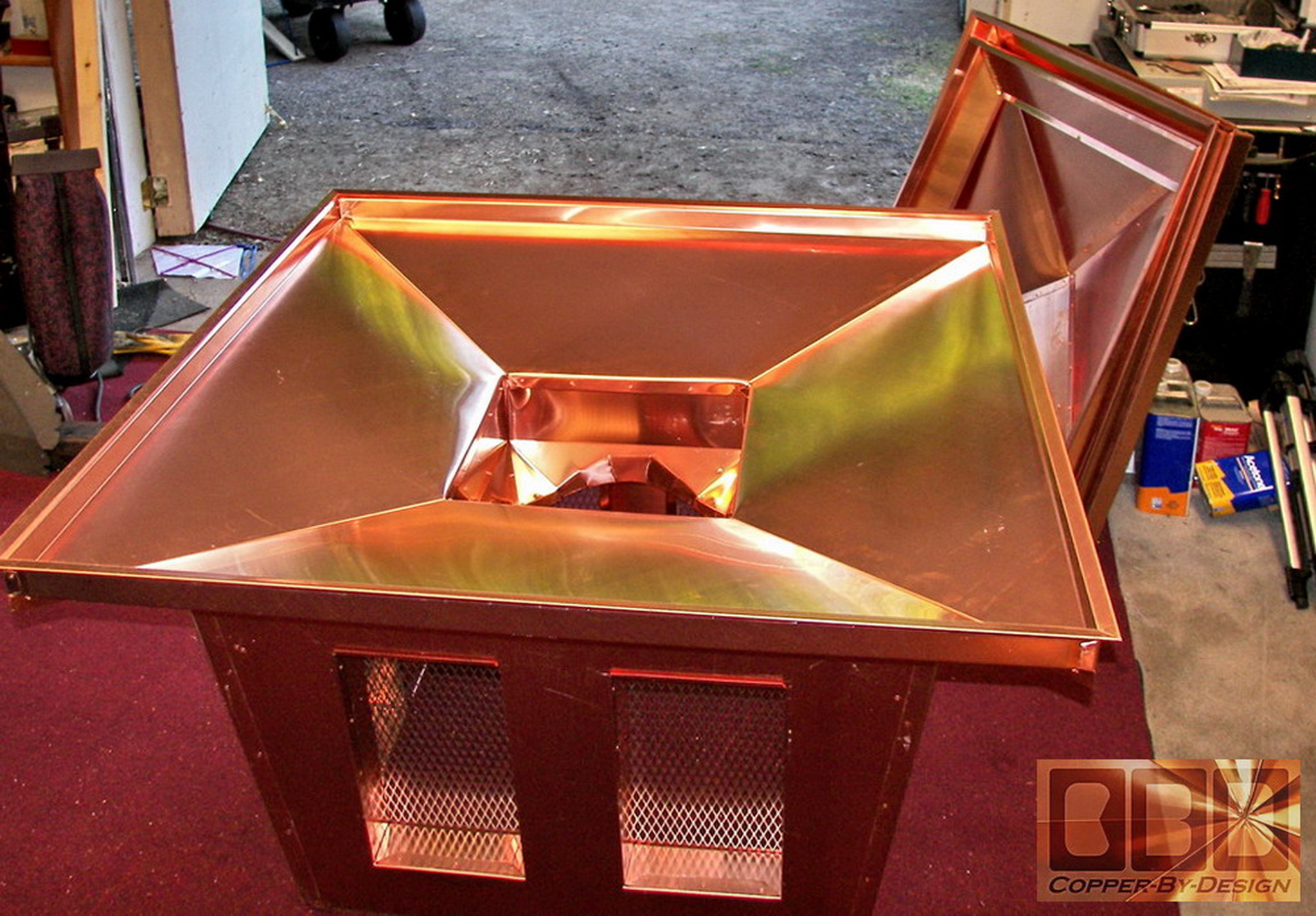
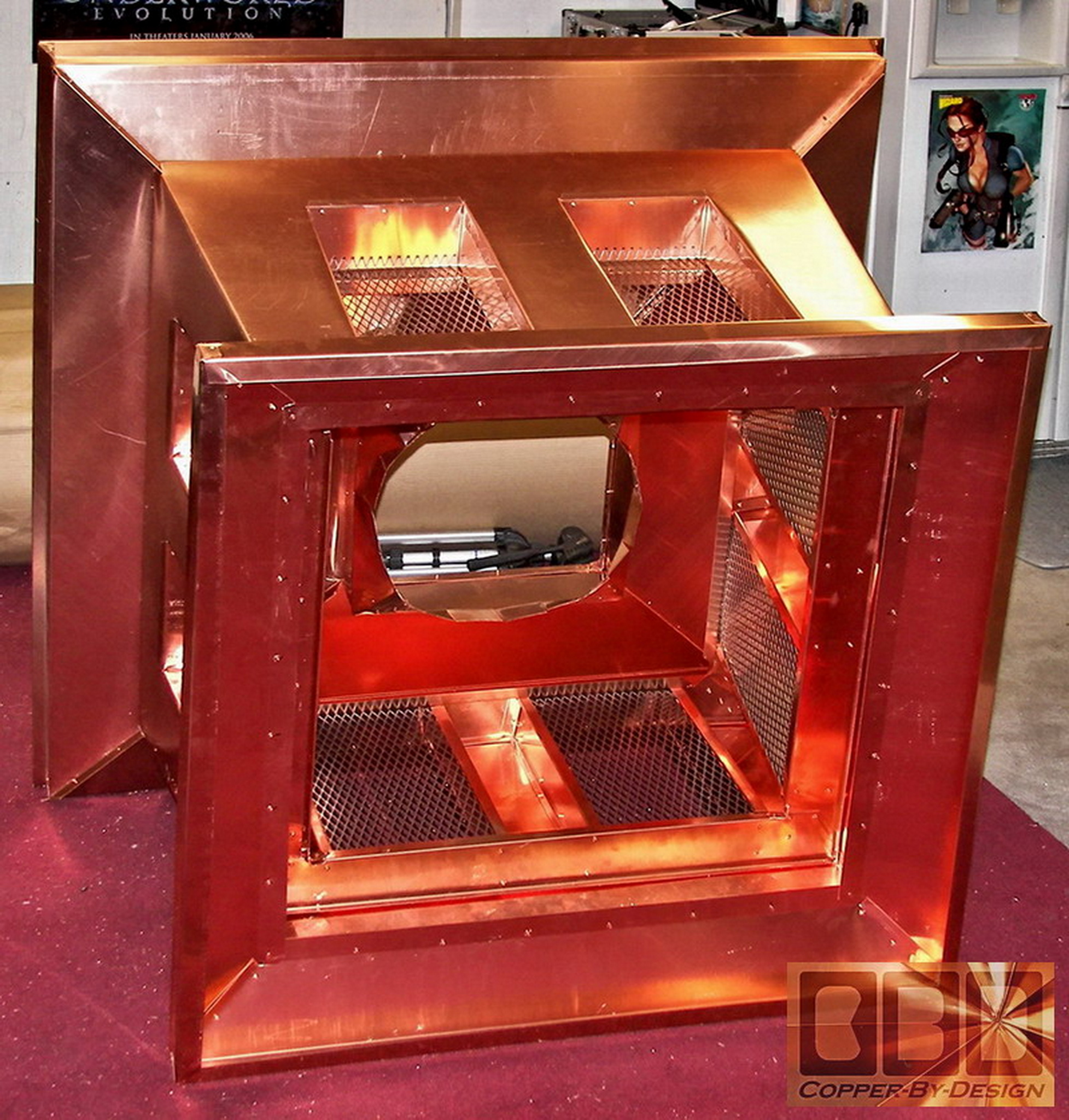
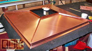
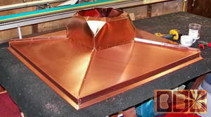
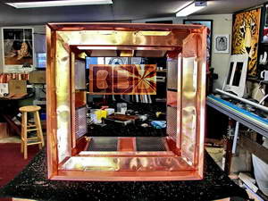
The first photo shows the roof section on it's
side from the underside, and half the pan formed. The second photo shows
the roof attached to the eave over the mid-section, but the pan base
is still not attached.
Here is the 4 sides of the pan base connected
together, and then the flue collar attached in the middle of the pan
to keep the rain out of the chimney below the chimney cap.
|
|
Building the wood crate for shipment:
To: Sunnyvale, California
(3/13/06)
|
|
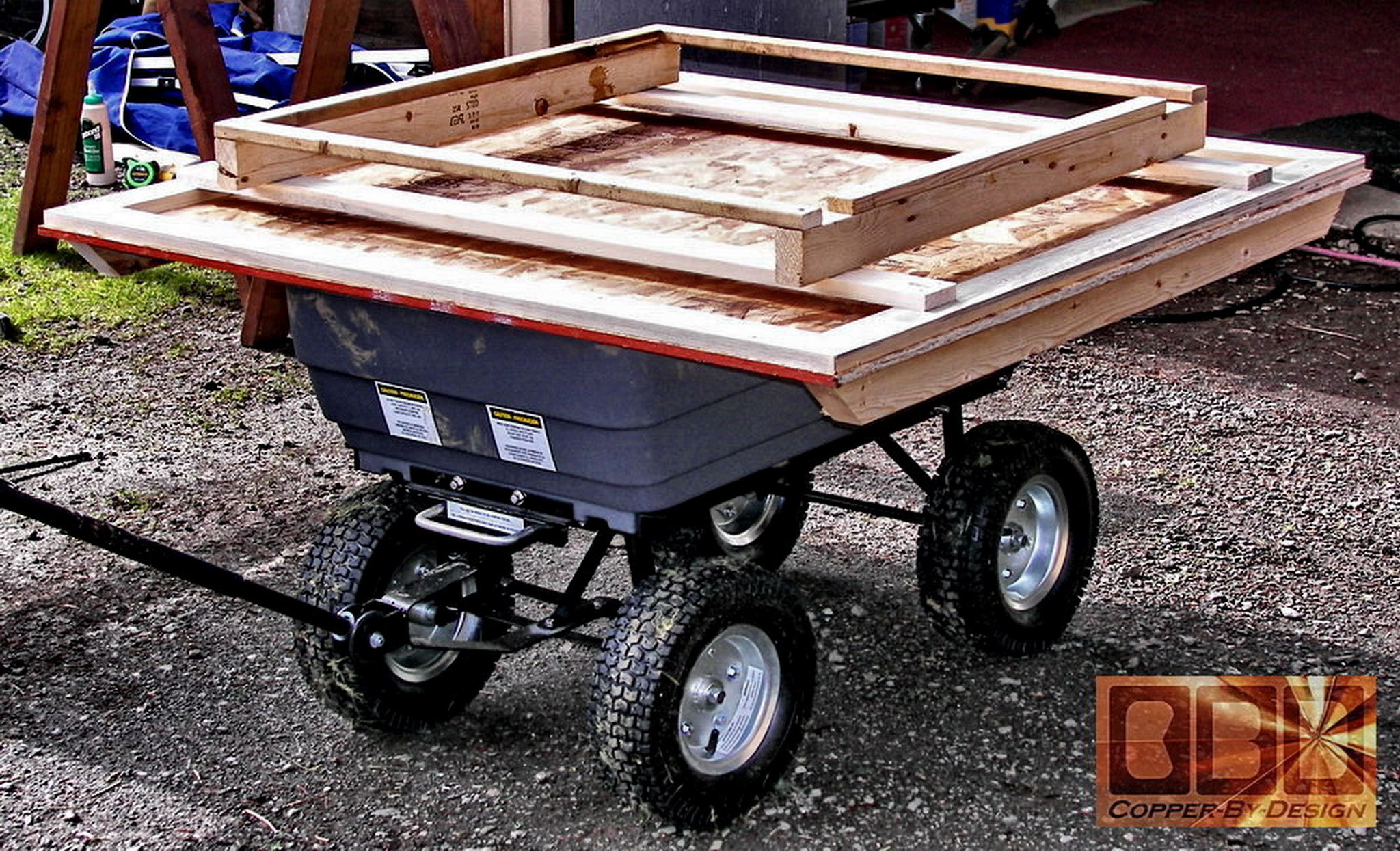
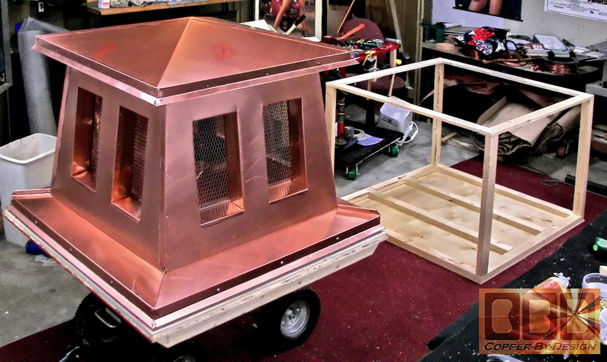
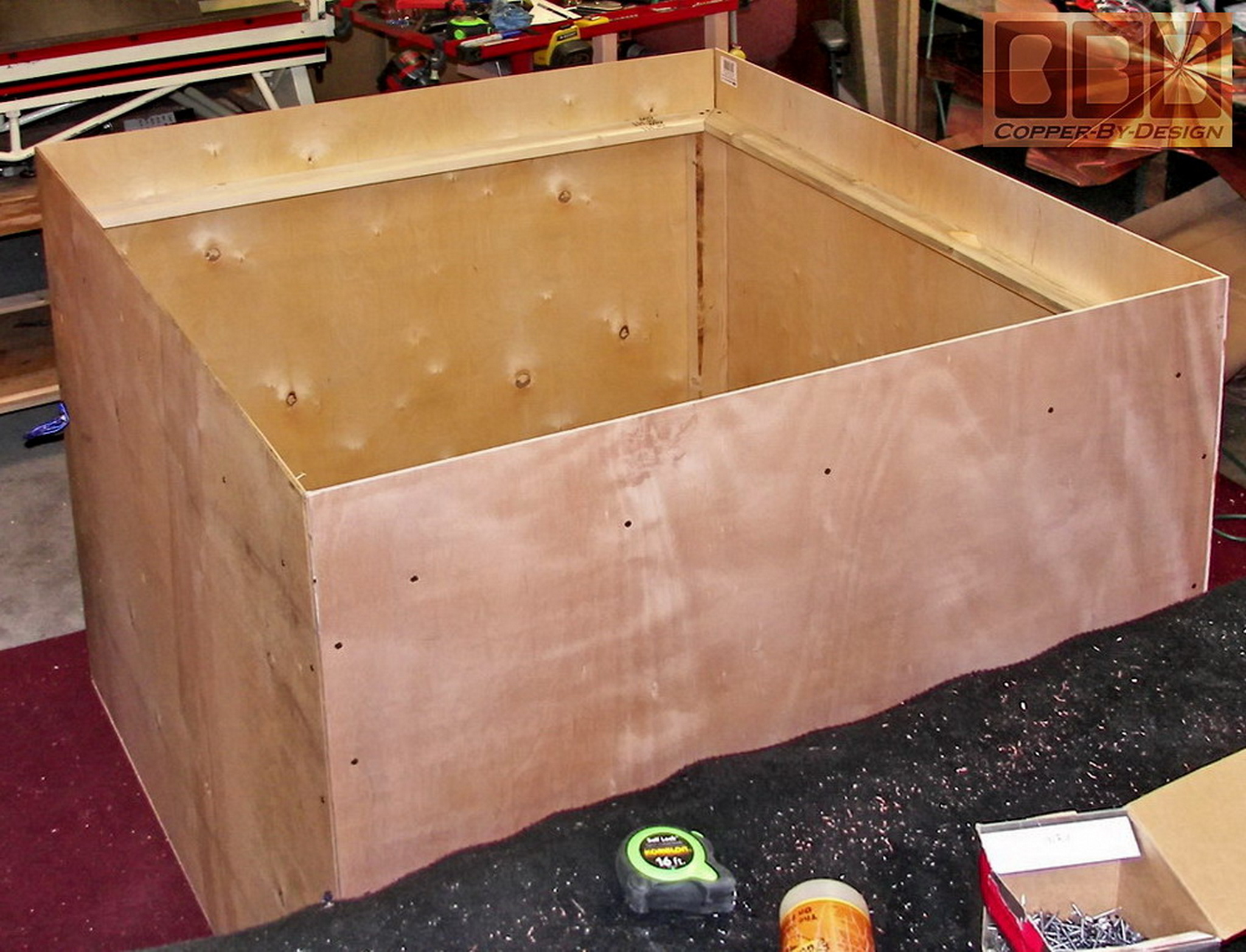
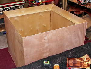
This shows the crate base with the internal support
I made to hold the weight of the chimney cap during transit.
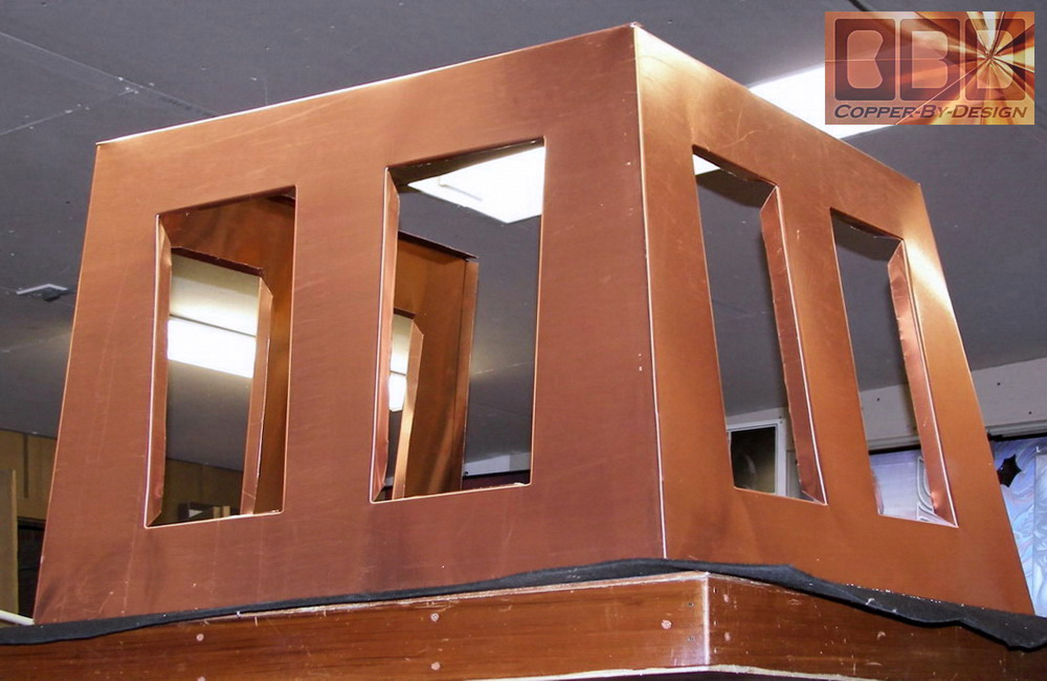
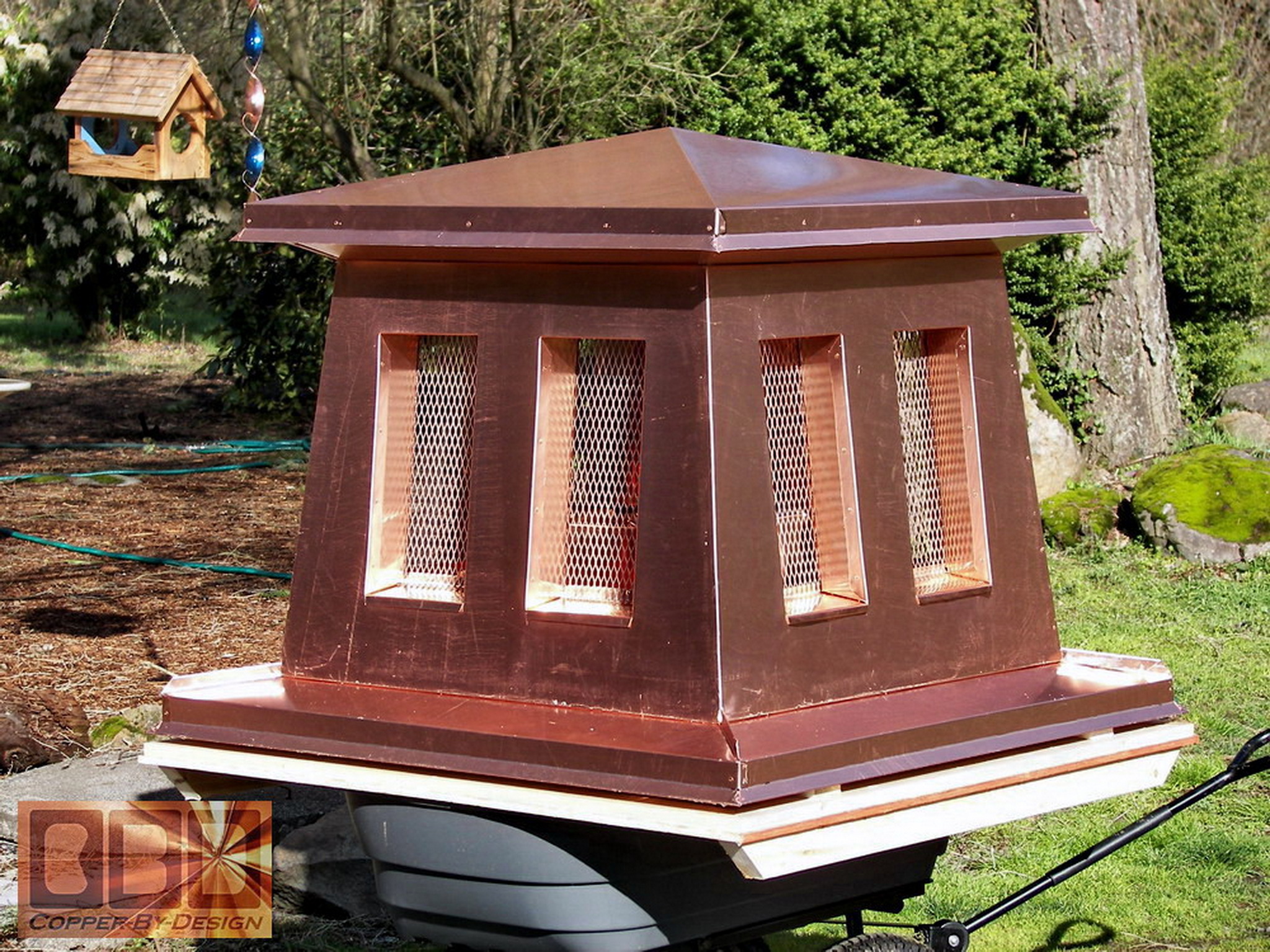
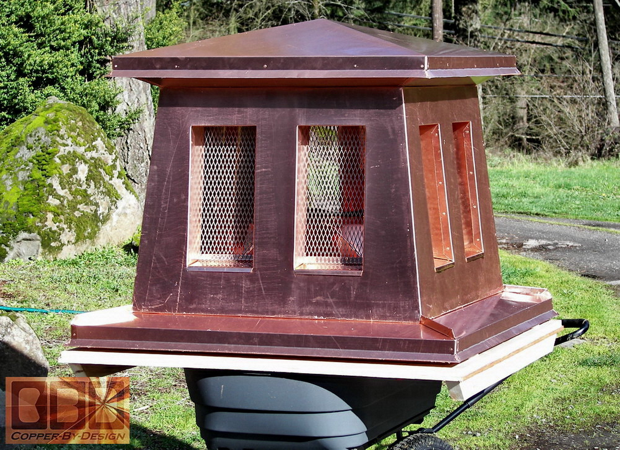
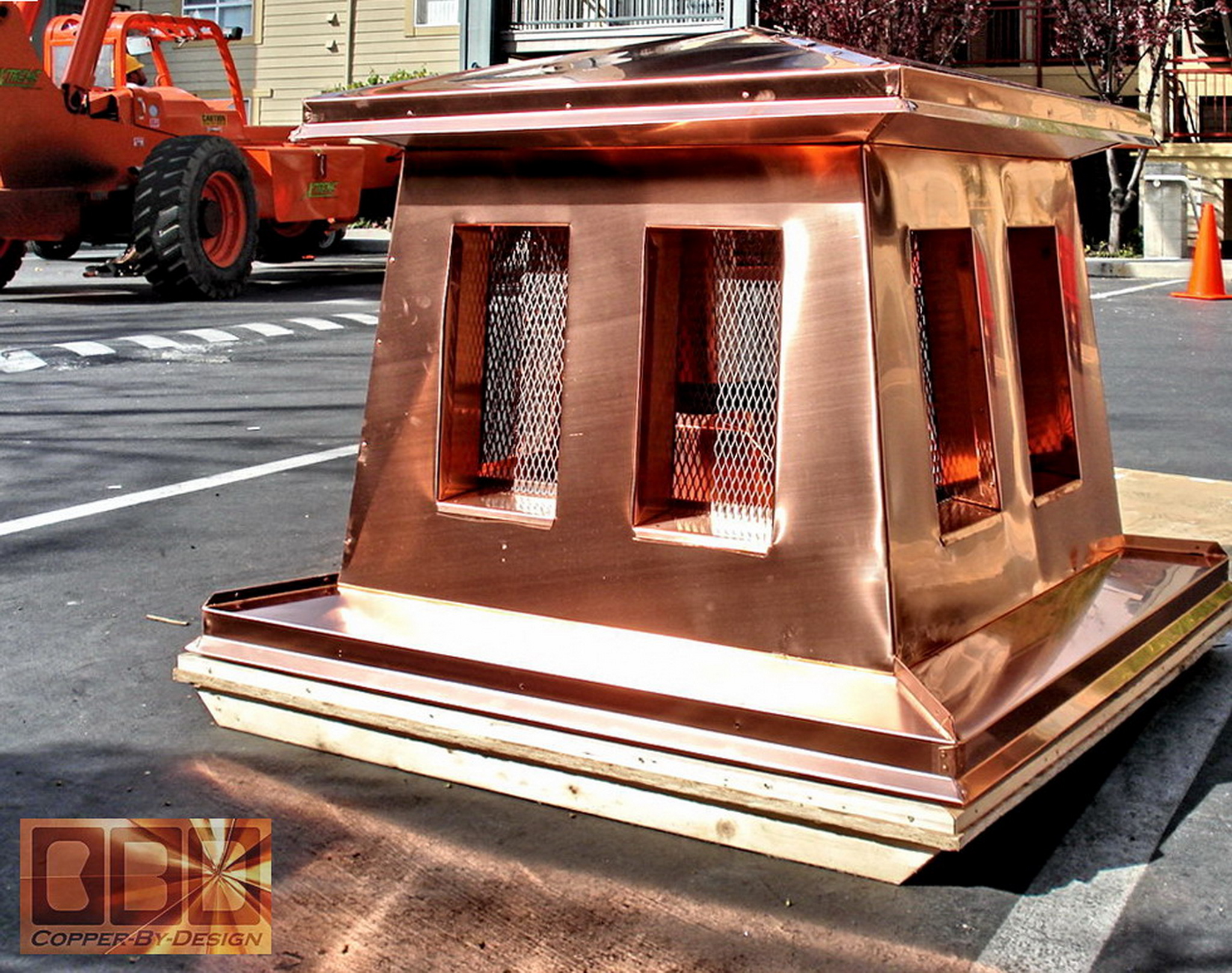
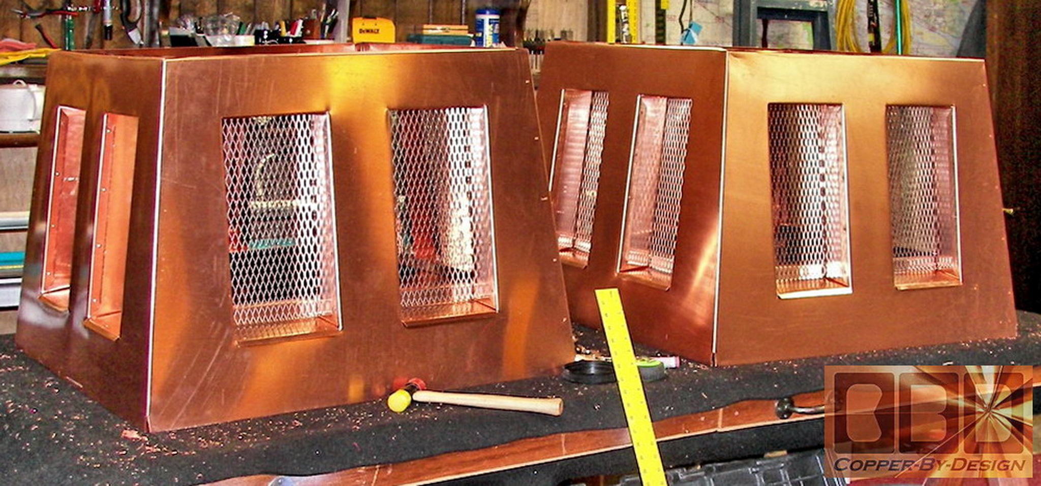
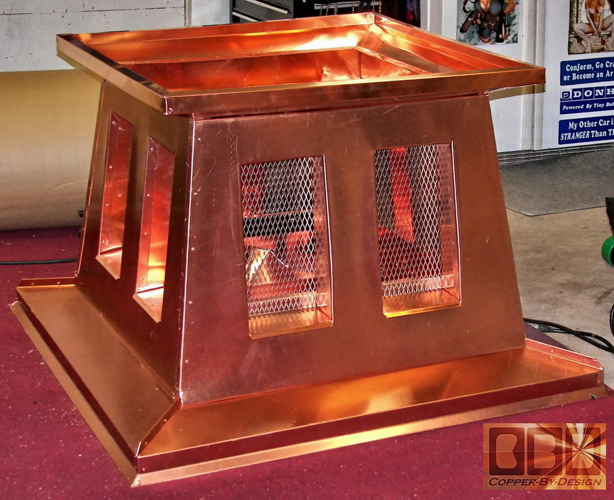
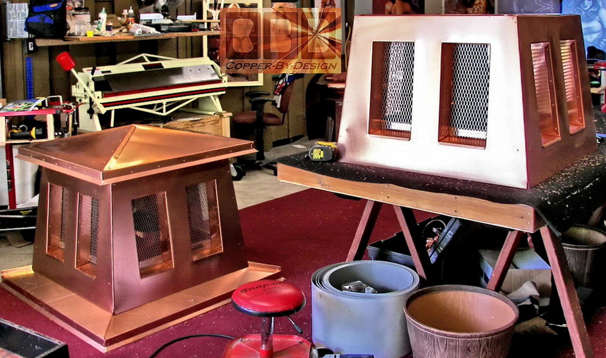
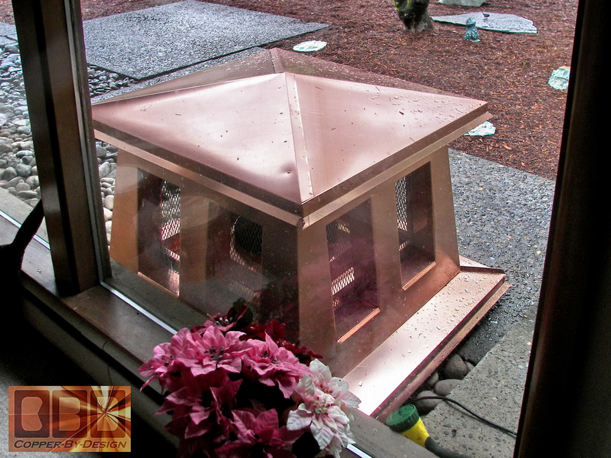
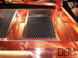
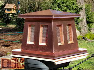
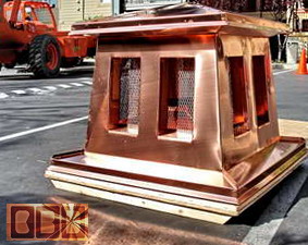
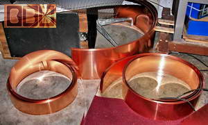
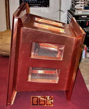
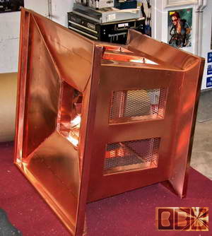
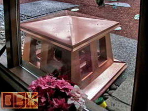
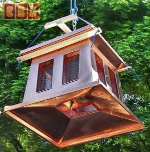
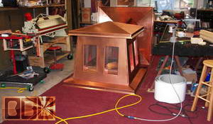
Here is the first chimney cap/shroud finished
set on the crate base out in the sun shine for it's photo layout shoot
posing for the camera (LOL). The copper looks a little different than
it did under the florescent lights in the shop.
 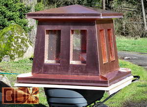
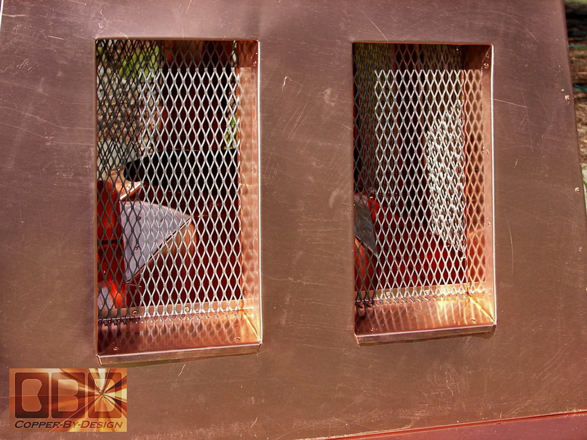
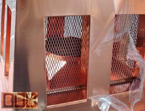
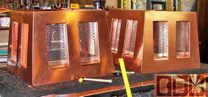
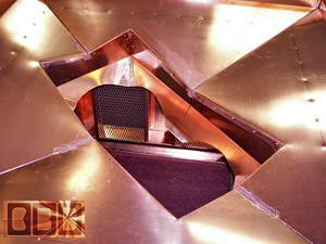
Here is another set of close-up shots of these
vents in sunlight for a better look at the finished product. We had
added a couple rivets to the bottom of the screen into the back bend
of the vent pan for better security and less chance for movement that
could scratch the copper below the screen.
Here is the upper shell of the crate being built
|
|
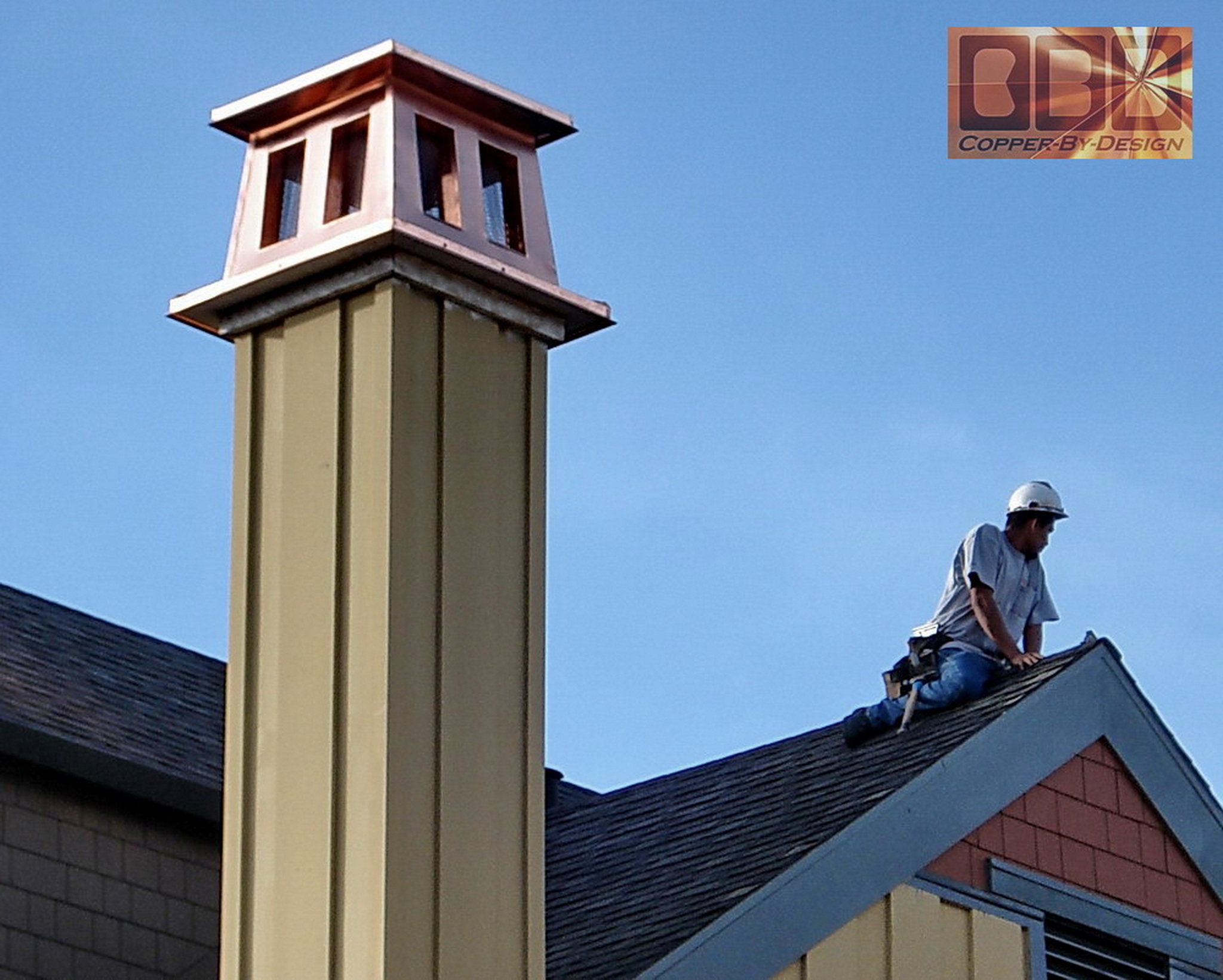
First chimney cap arrived and installed:
To: Sunnyvale, California
(3/20 to 23/06)
|
|
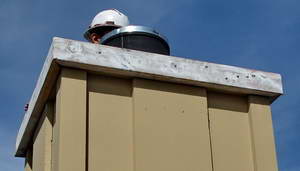
This shows the first unit after it arrived to
Sunnyvale California at the job site. They caught a photo of the process
of pealing off the clear protective plastic film from the outer surface
of the copper. We had removed all the film from the copper that they
would not be able to access.
This shows the copper chimney cap ready to be
installed still resting safely on the crate base. The edges of the pan
base can handle the weight of the chimney cap, but if they were to set
it down a surface that was not flat or on a rock, that could tweak or
dent that bottom edge, since the whole unit weighs about 100lb.
 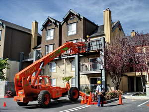
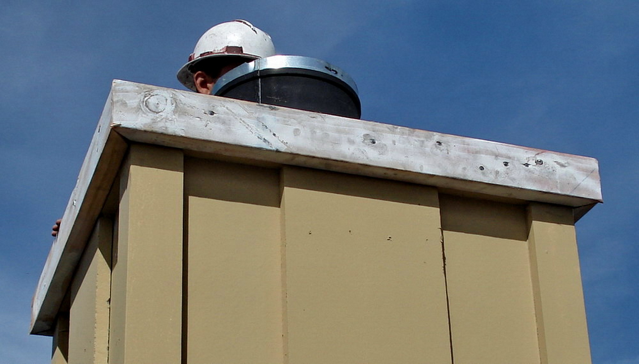
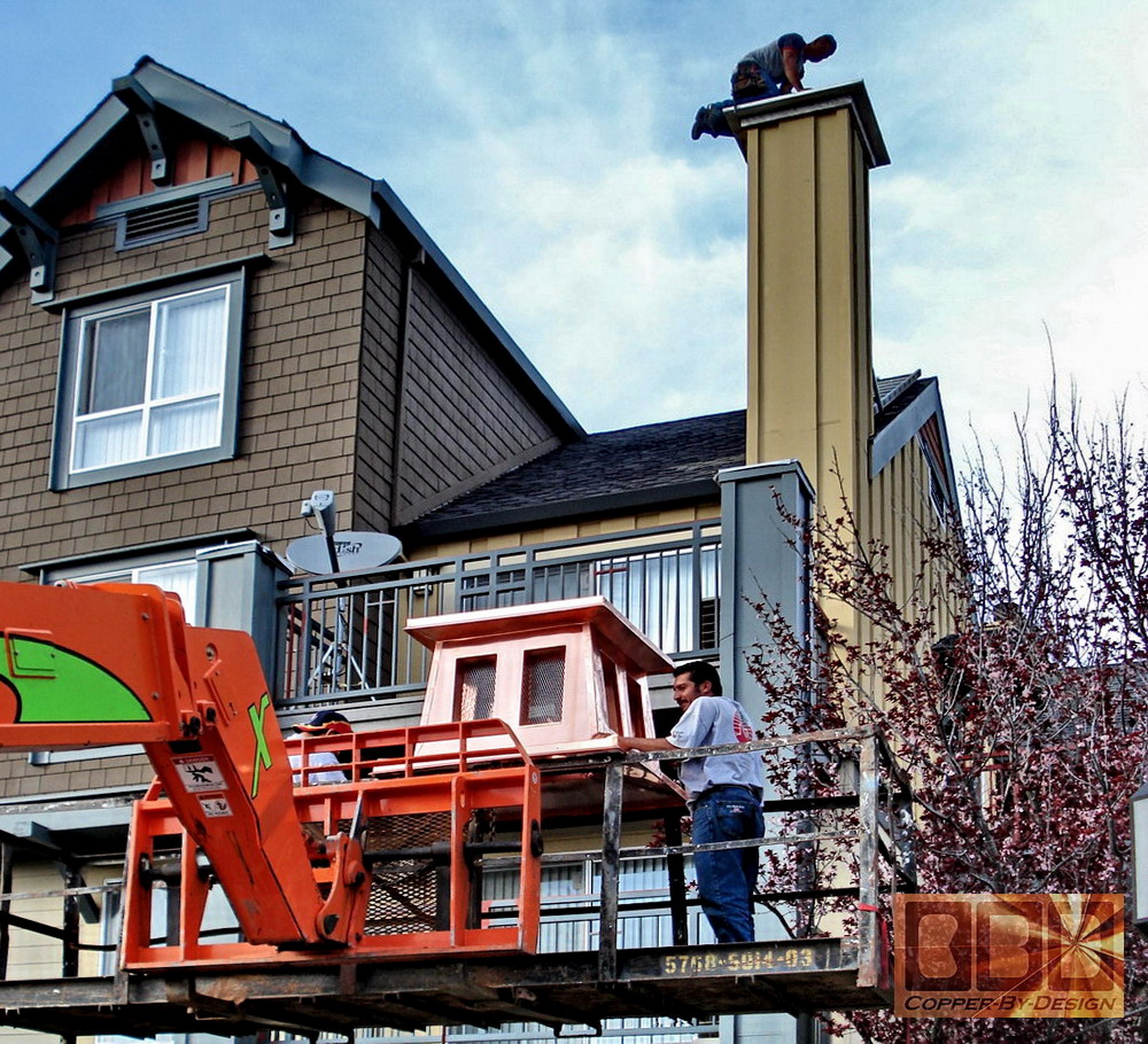
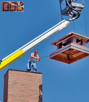
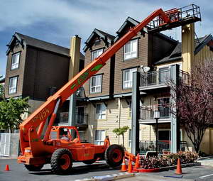
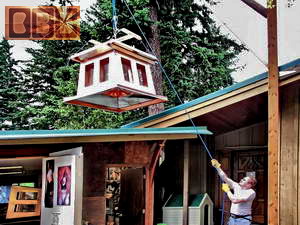
They used this powerful lift vehicle to get their
carpenters up to the top of the chimney to remove the original pan and
chimney cap. Then to add the wood that this chimney cap will rest on
and attach to.
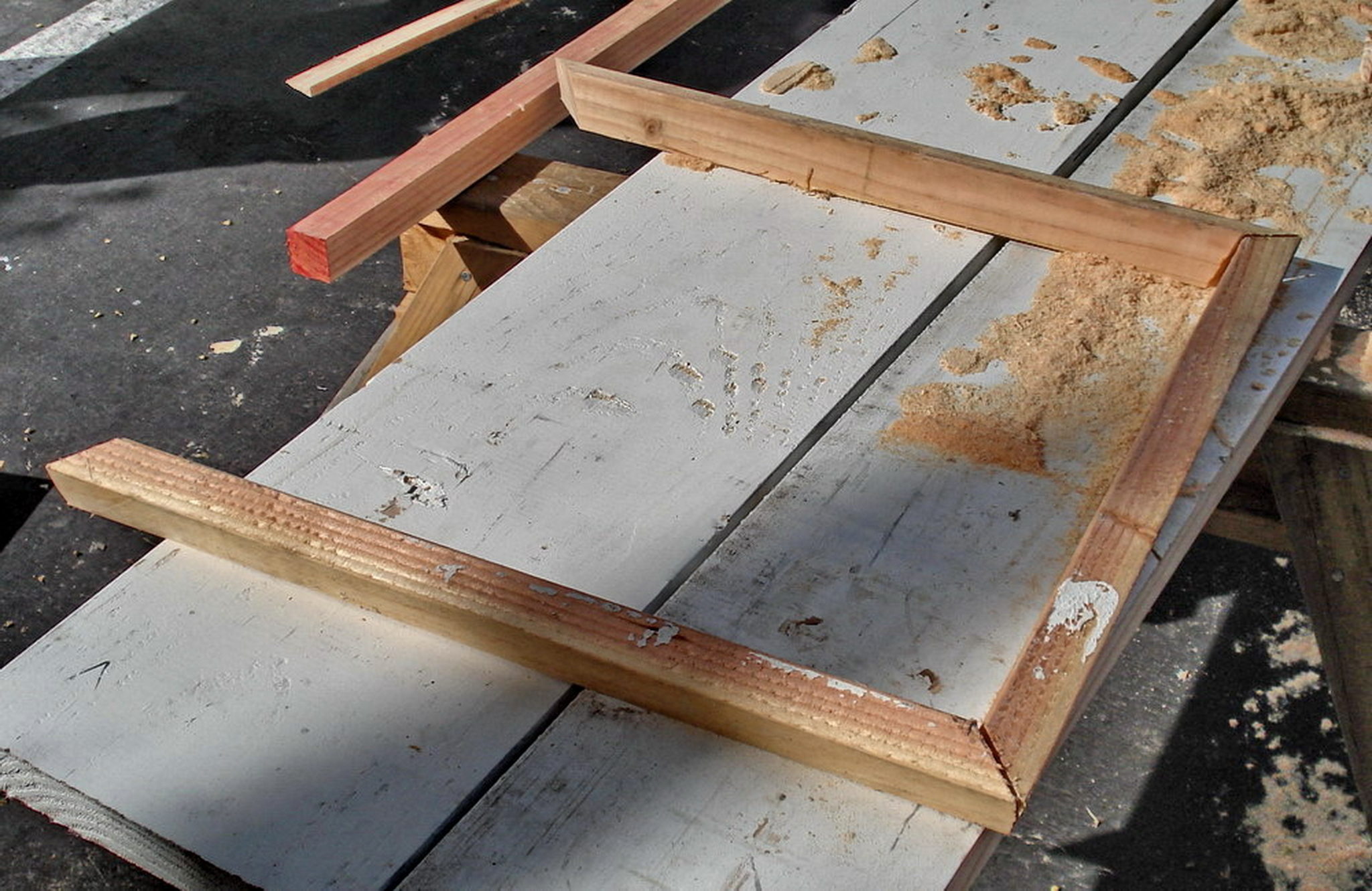
They had me build these several inches wider than
the original chimney top for an aesthetic advantage, so the top needed
to be built out and made at an angle that matches the angel of the copper
pan base We had made.
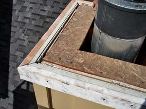 
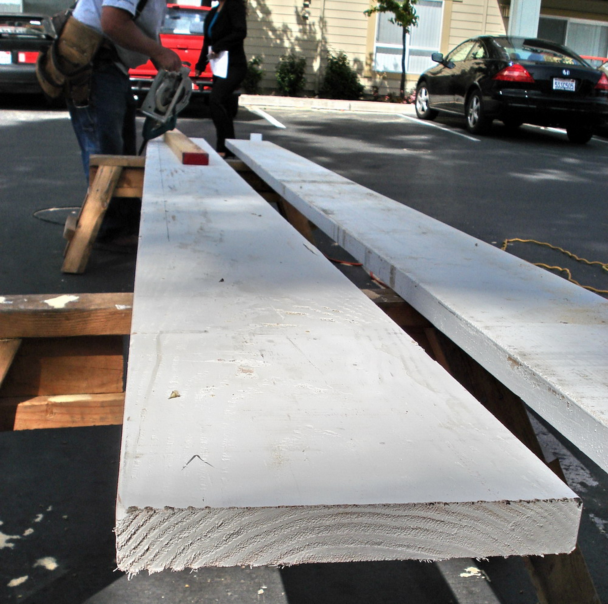
These are the primed 2x12 they used to make this
extended base for the chimney cap to rest on with a decorative 2x3 wood
frame to attach under this base edge, but for some reason they decided
not to use this smaller frame. I assume they had messed up their measurements
and scrapped the idea I had suggested.
Knowing that they would be hard pressed to get
their carpenters to build this wood base frame just right I had offered
to build them all the custom wood base frames with trim the boards,
but the project manager decided they did not want to pay that added
cost, and felt their Hispanic carpenters could handle it there at the
job site. It seems they were wrong.
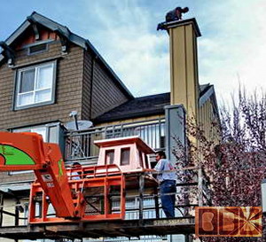 
Here is some photos of the chimney cap going up
for attachment. We had suggested they lift it from under the platform
by ropes just under the roof of the chimney cap, so they can just set
it on the chimney box without any obstructions, but it seems that was
too complicated for them to figure out and communicate to their workers.
|
|
Preparation
of the many parts:
|
|
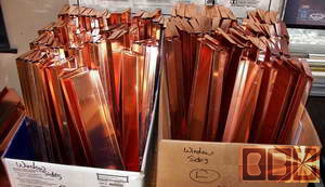
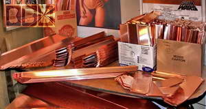
We were able to use up all the left over scraps
we had accumulated over the last few years with making these smaller
parts and finally decided to scrap the pieces that were even to small
for this project, since we would most likely never use them up. We needed
the space. That is when I found out copper prices had taken such a huge
leap we have never seen before. It had already doubled since I had last
taken some copper scraps in for recycling. By the end of this project
the scrap value of copper had tripled.
This of coarse meant that new copper sheets would
cost more. They did double in cost and ate away at our profit margin
quite a bit, but we were stuck in the largest contract we had ever gotten.
I also lost money on several copper gutter bids we had sold before I
realized copper was getting so expensive. It had not fluctuated more
than 10% in the last 15 years. There is no way we could have imagined
copper and aluminum would have taken such a leap.
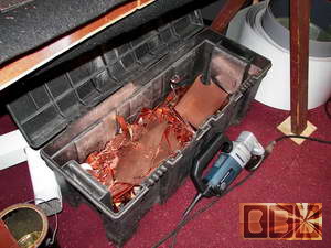 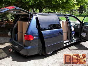
This is a 4' wide plastic case I toss small cut-off
scrap copper pieces in. The other photos shows our van loaded with 33
sheets of the 20oz copper. That is 1.25lb per square foot x 30 sq' =
37.5lb x 33 sheets = 1,237.5lb, or around $8k in copper. It took a total
of about 80 sheets in all to fill this order. During this time we recycled
867lb of copper and 38lb of brass from the copper rivets. That copper
equates to over 23 full sheets of copper that was small cut off scrap
of less than 1 square foot pieces.
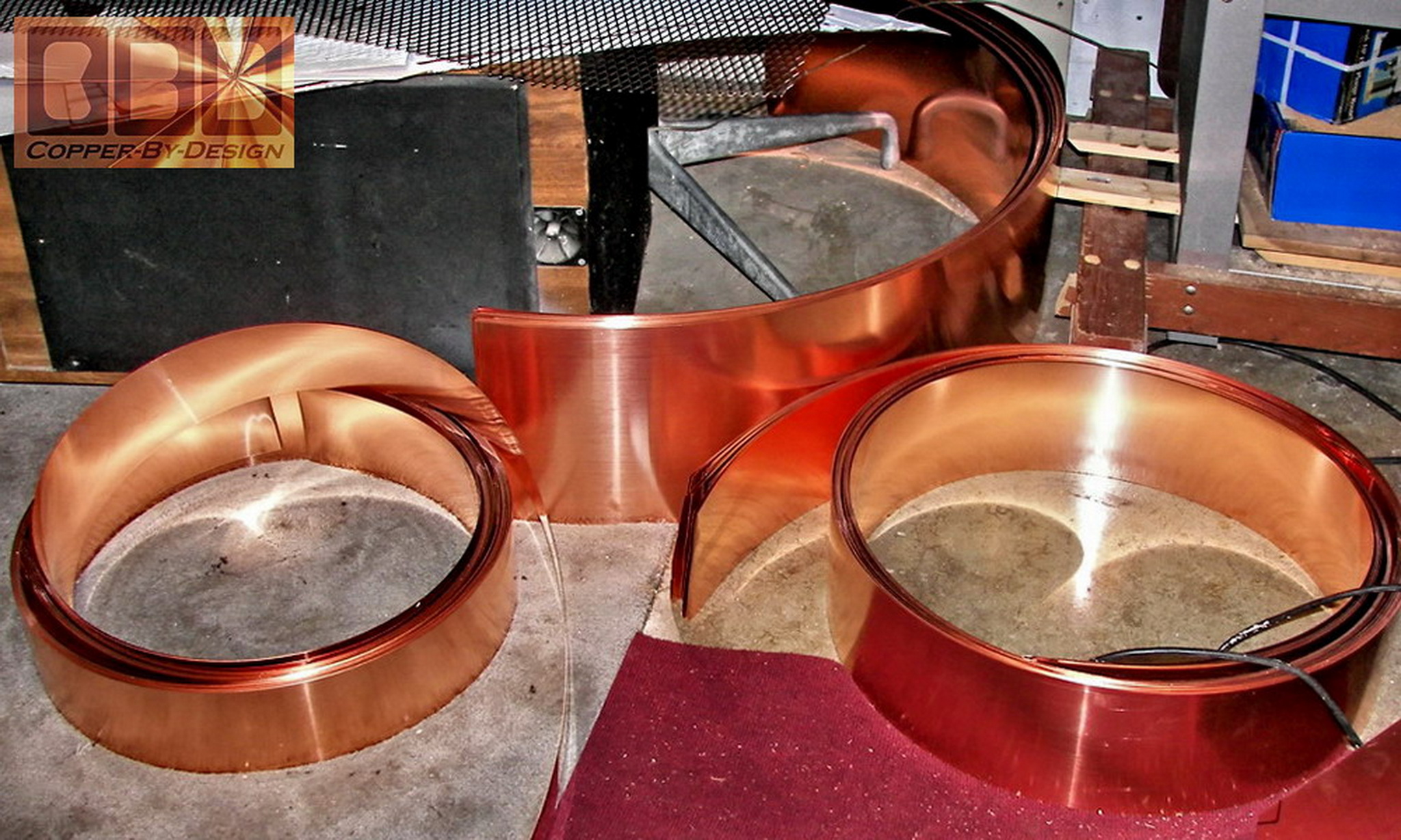
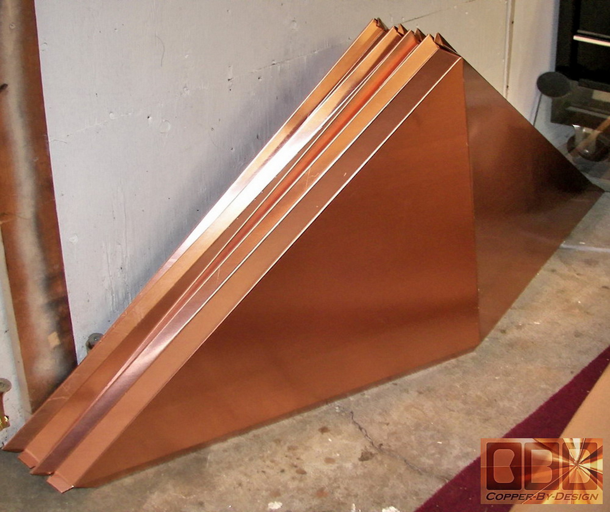
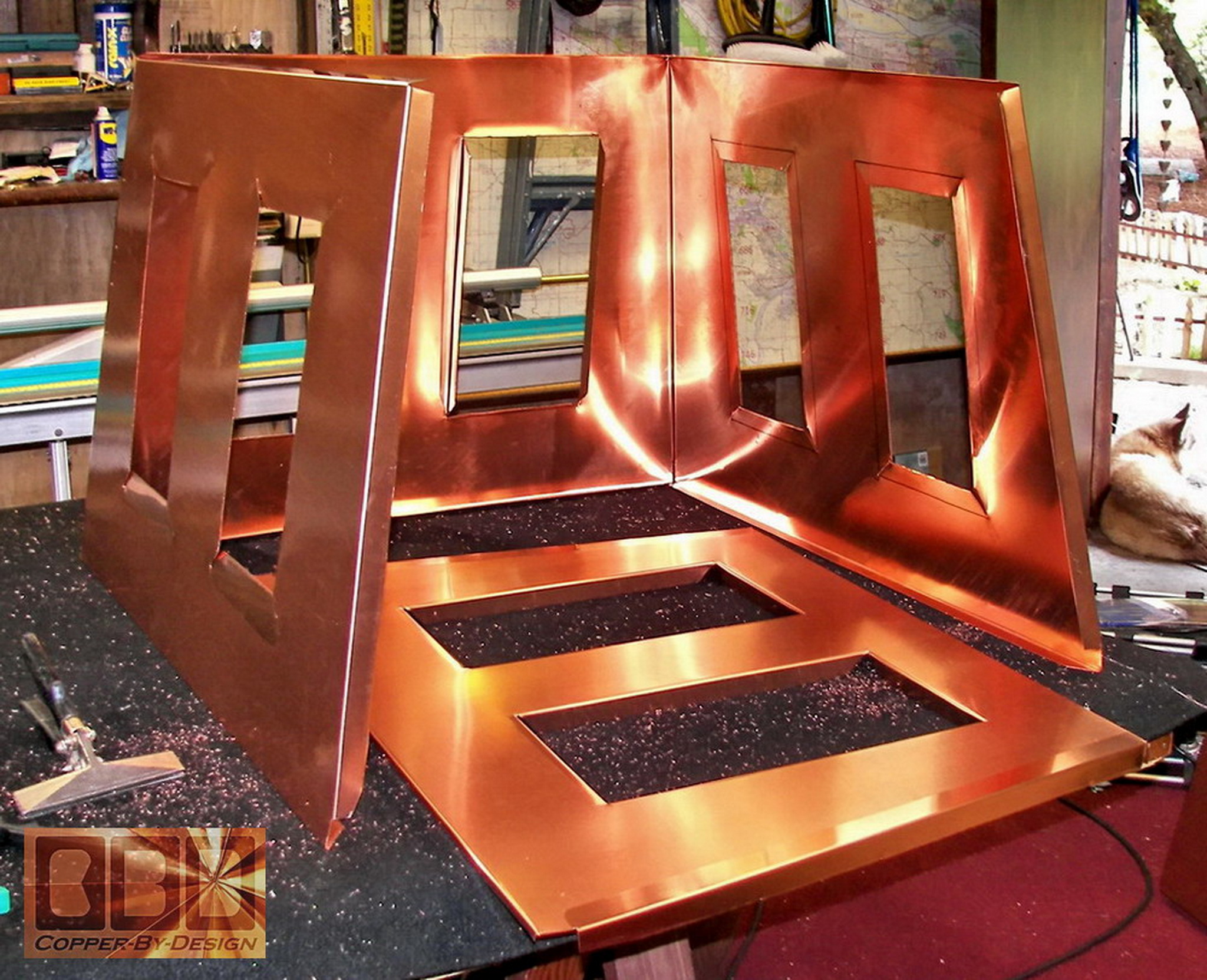
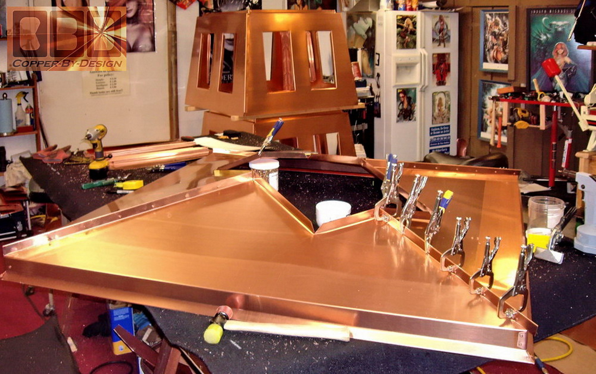
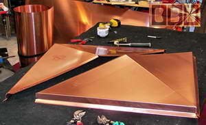
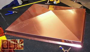
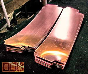
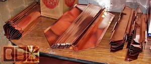
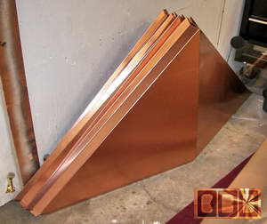
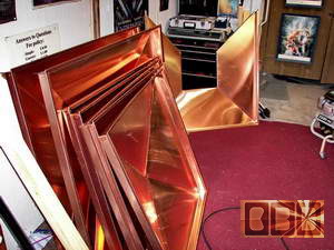
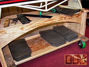
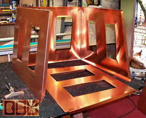
Above is the pieces cut out for the 1/4 sections
for the pan bases flat and bent into shape. Below are half roof sections
bent into shape and formed, leaning against a couple assembled pans,
with one 3 section pan yet to be finished in the background.
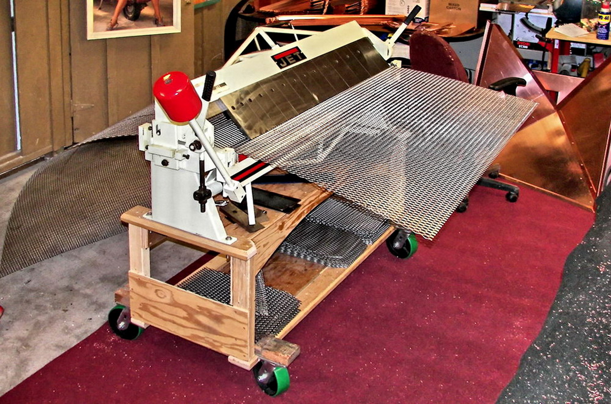
This is our 4' wide bender sitting on a custom
stand over heavy duty casters. It is holding the stainless steel screen
for cutting. It is adjustable and has an unlimited depth. It is also
stronger to bend thicker metal like this SS screen.
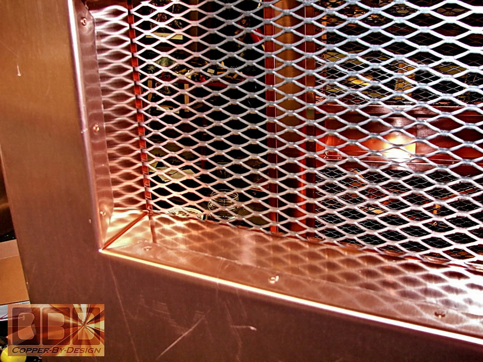
Above is the stainless steel screen sheet to be
cut for these small vent opening for spark arrest and to keep unwanted
pests out of the chimney caps while not in use. We have not found a
source for copper screens, but this works good, since it is stronger
than copper, which is very important where it comes to an expanded metal
screen that has a compromised strength as it is. Also, it will just
turn black with use, so it will not be seen as stainless steel.
|
|
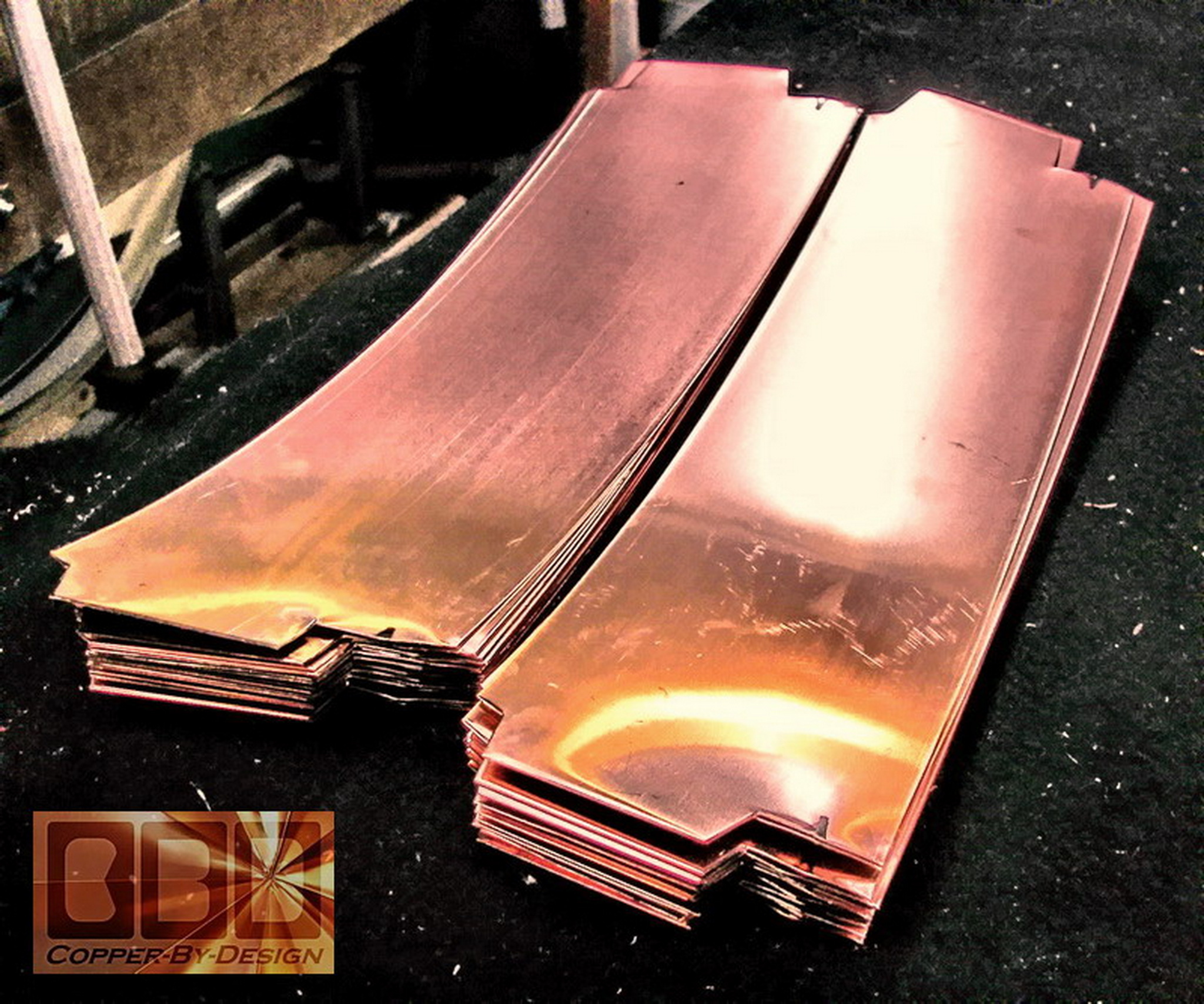
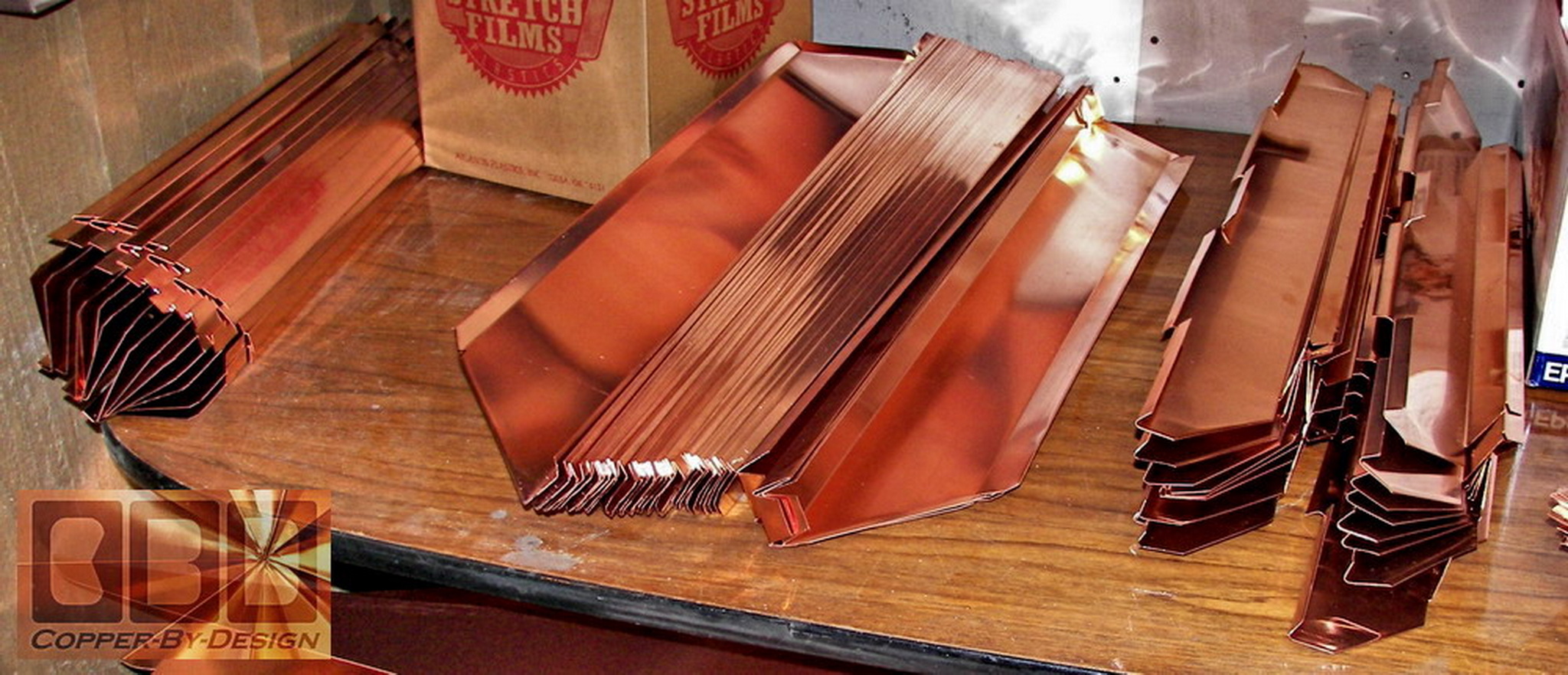
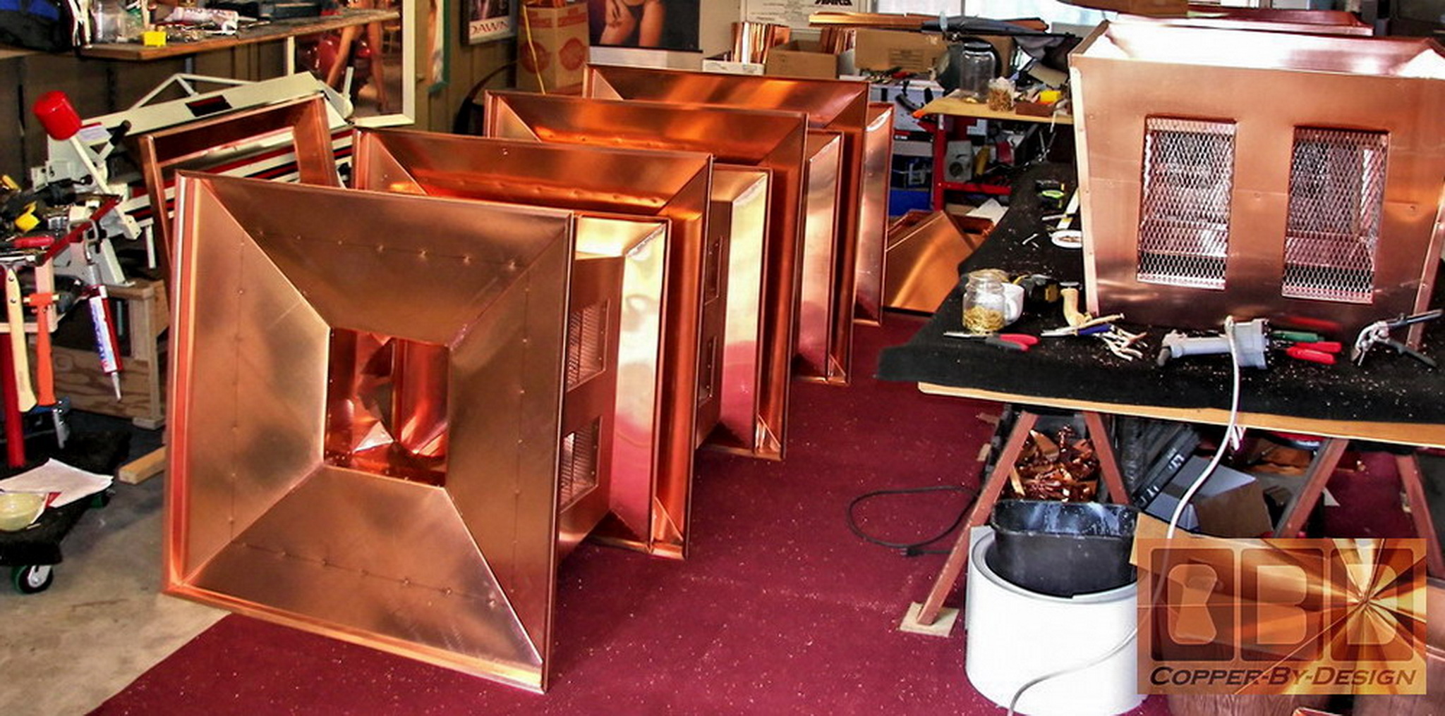
Preparation
of the mid-section shell:
|
|
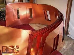 
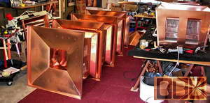
Above is the mid sections being cut and bent into
their 3 sided shape. Below is the forming of the fourth side of the
mid-section. The silver and green machine is the main metal bender we
use that is 10.5' wide, but has a limited depth of only 14".
Here is the fourth side being attached to the
main part of this mid-section.
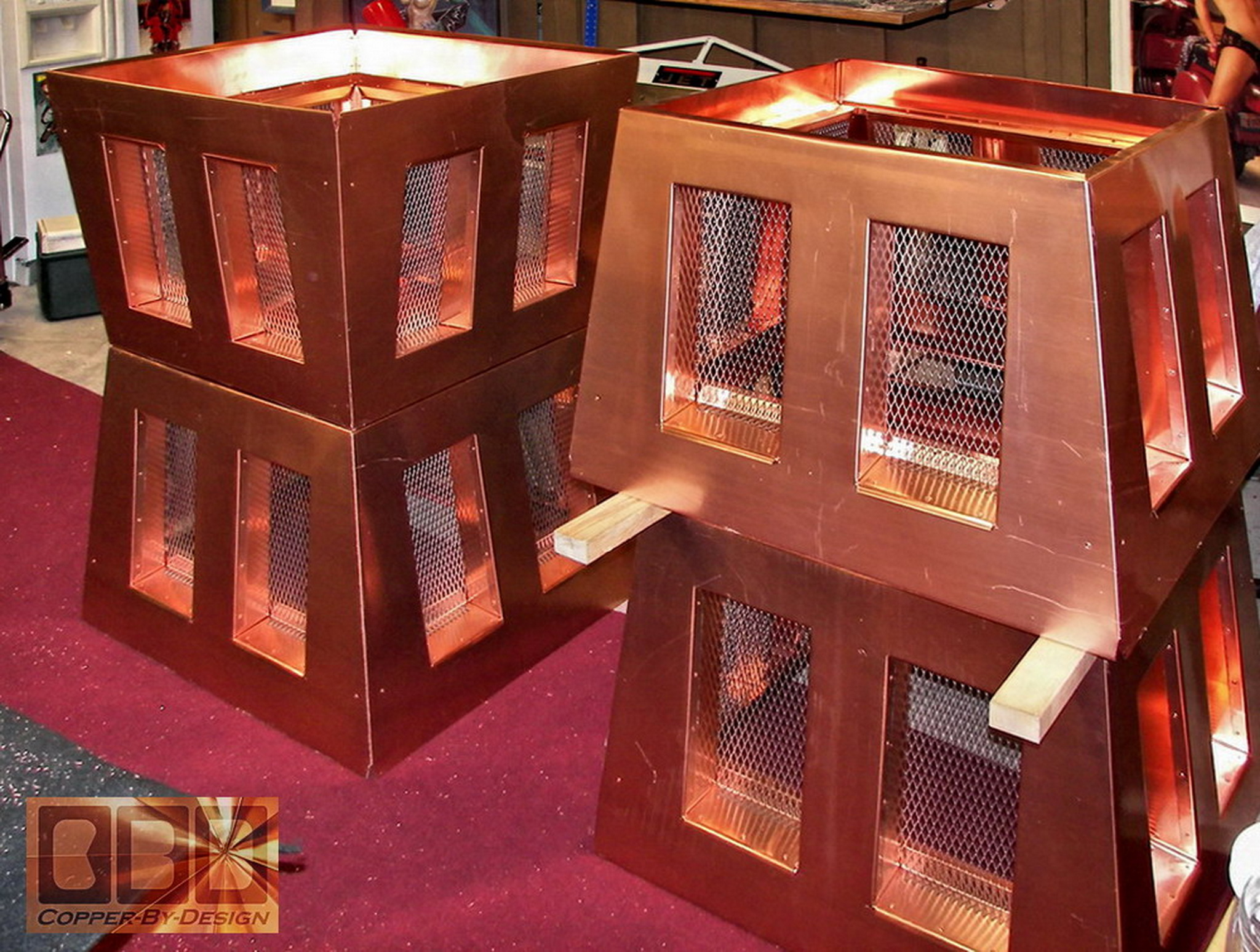
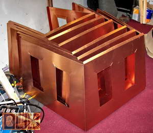
Here is several midsections stacked to make space.
It is easier to process several at a time, so we are not going back
and fourth between the tools we need, as well as having these processes
fresh in our mind.
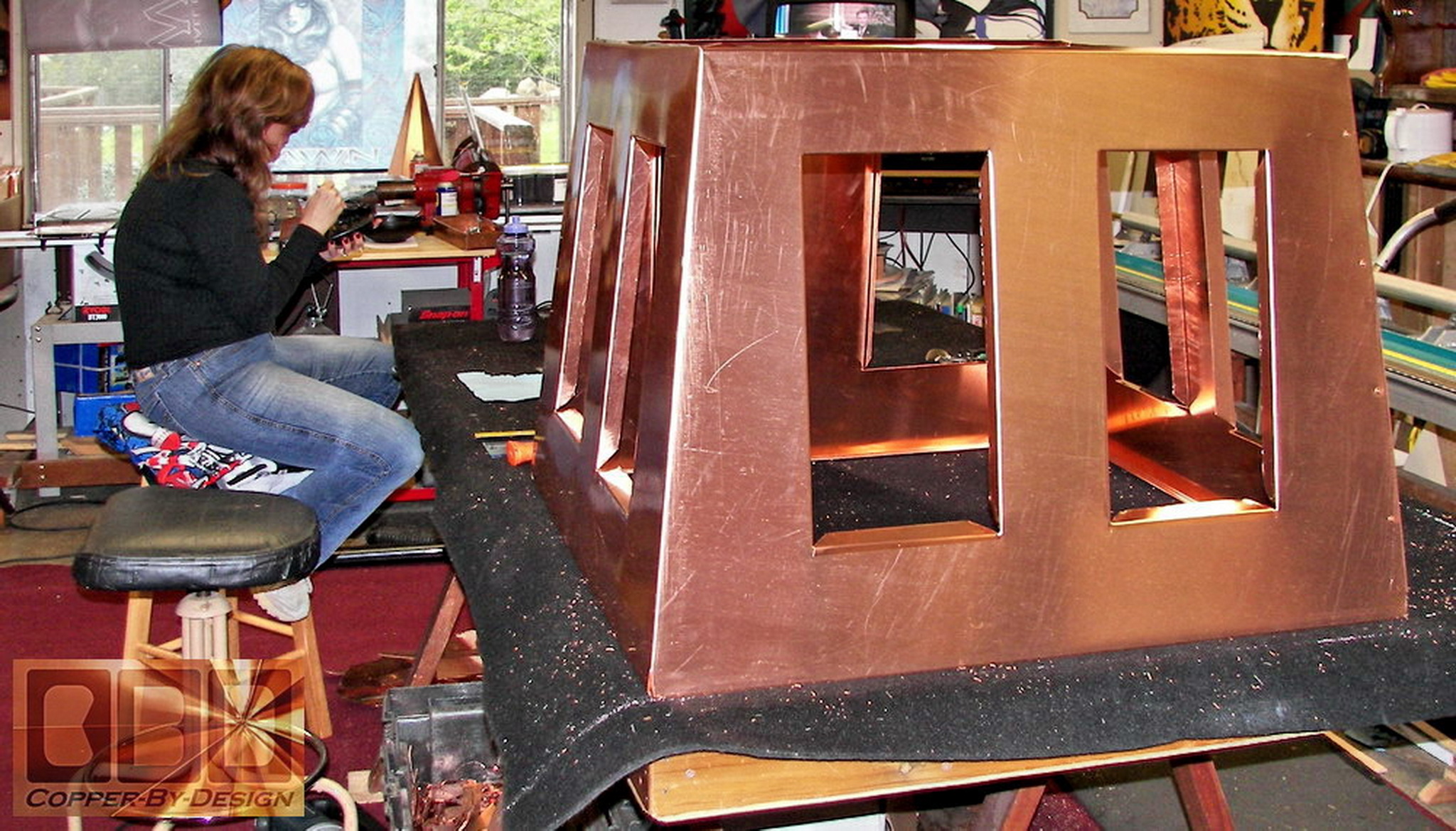
We would rotate a set of 2 mid-section while assembling
the inner framework. I would set and clamp the pieces in place, drill
the holes for the rivets, while Tia would follow behind riveting them
together.
|
|
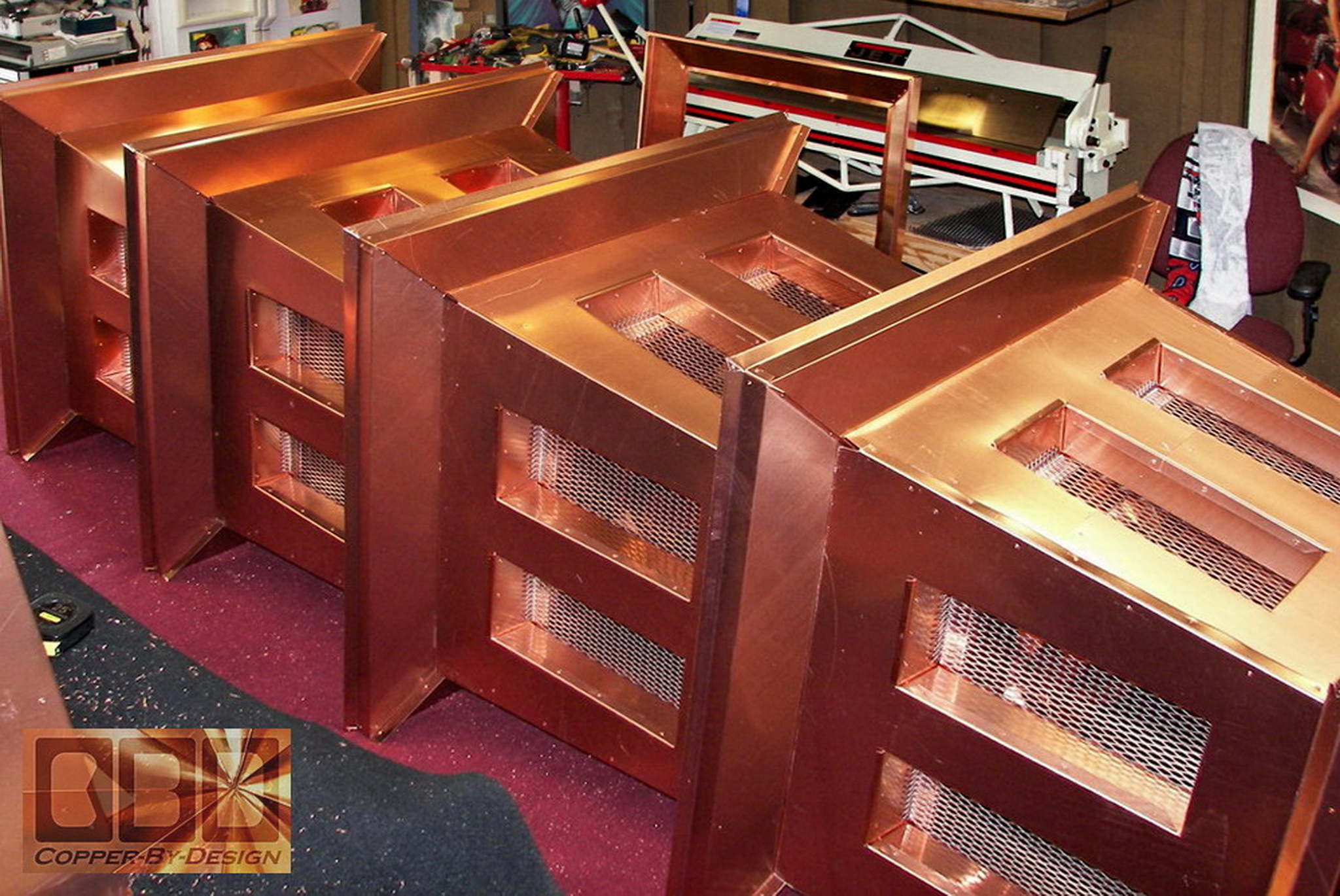
Assembly of
the venting framework inside the mid-section:
|
|
 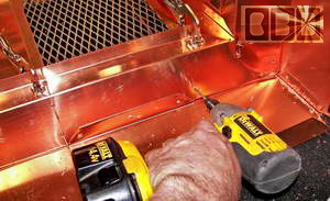
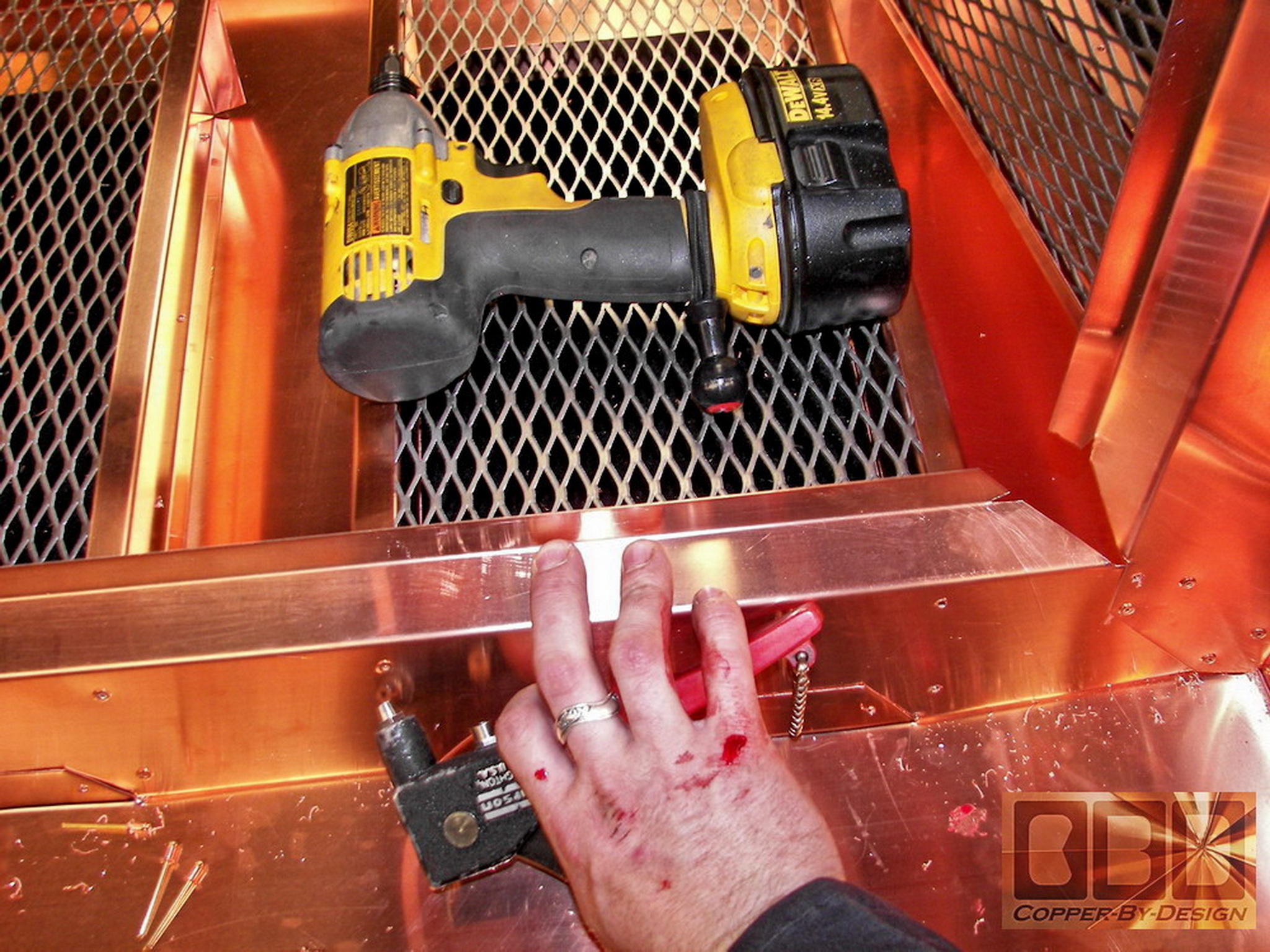
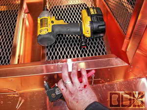
This is my hairy arm, and yes that is my fresh
bloody knuckles in the lower right photo. I cut up my hands quite a
bit working on this part of the fabrication on the sharp edges of the
copper and stainless steel screen. Tia was smart to wear leather gloves
for most of it, but I found it too limiting.
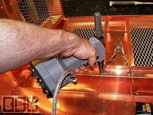 
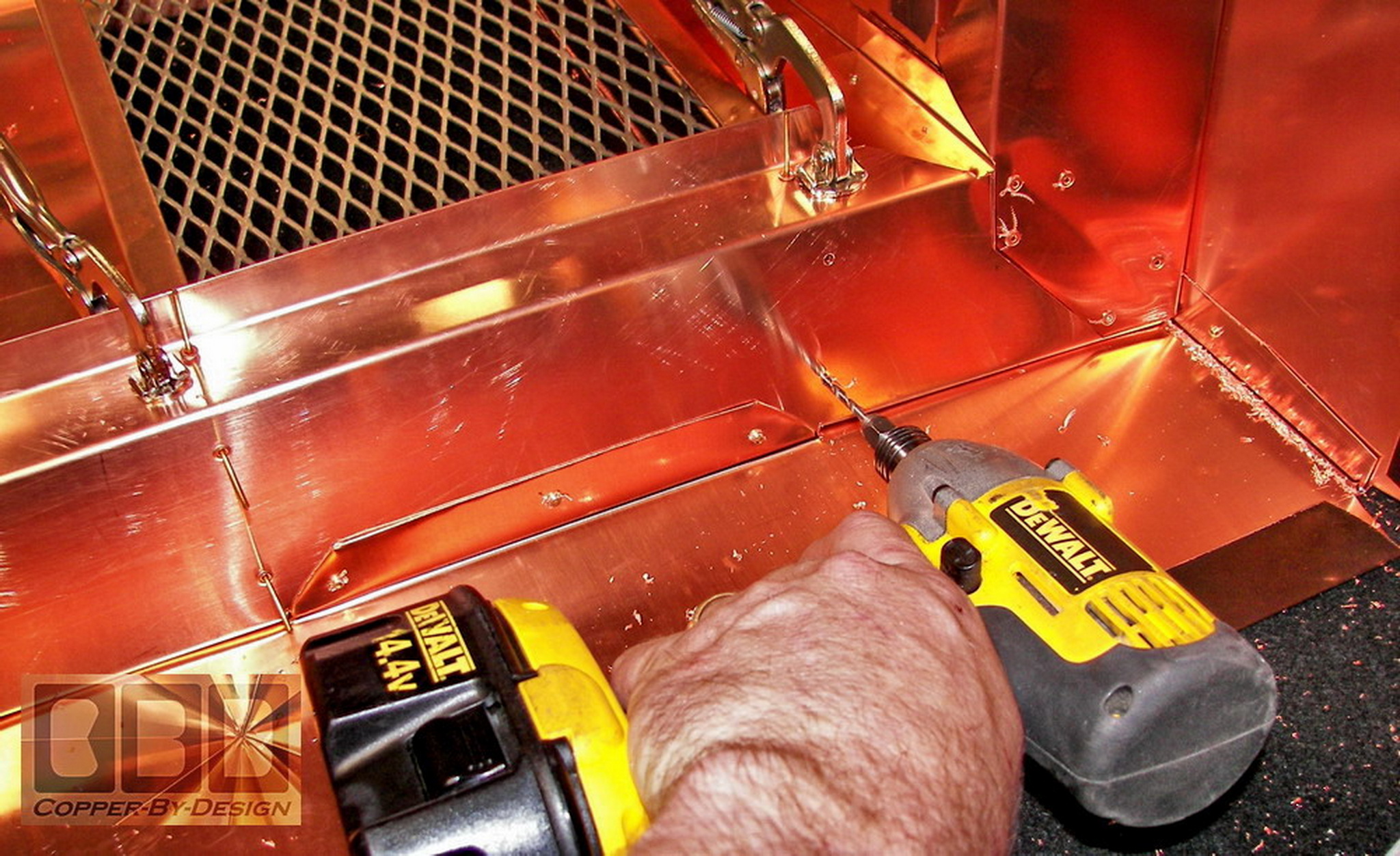
Because of the potential heat that could be generated
inside these chimney caps, we have to assemble these with rivets and
no solder (that could melt and fall apart). We had to make sure these
would be strong enough to last through this century or longer. They
may need to withstand 100mph winds and earthquakes.
As mentioned earlier; I counted over 500 rivets
that went into each chimney cap unit, yet there are only a few dozen
that could be seen from the ground using binoculars. After it has had
a chance to tarnish, they will be hardly noticeable, but we strive to
design and build the best looking, yet still the strongest fabrication
around. You will be hard pressed to find another shop willing to spend
the time and effort we do.
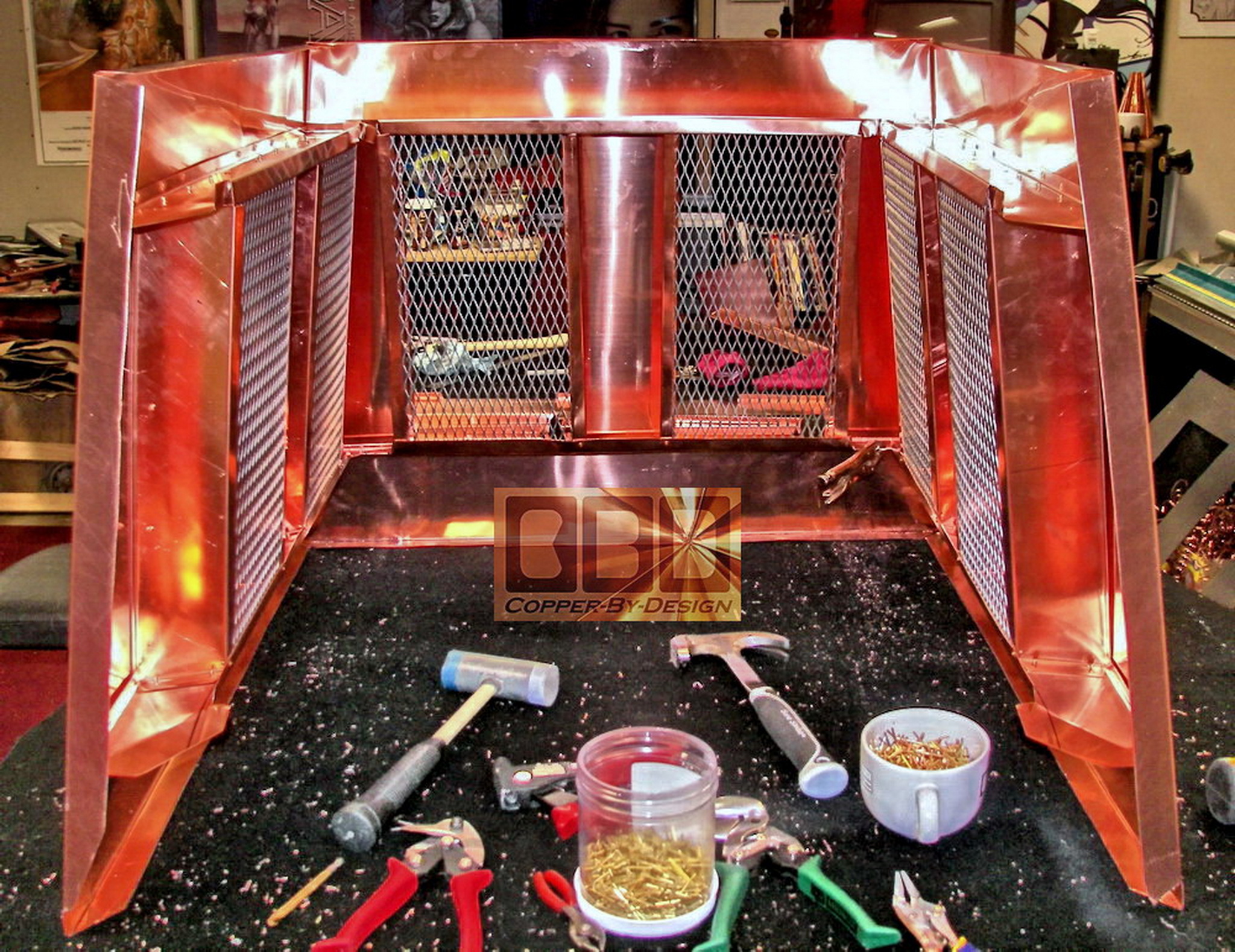
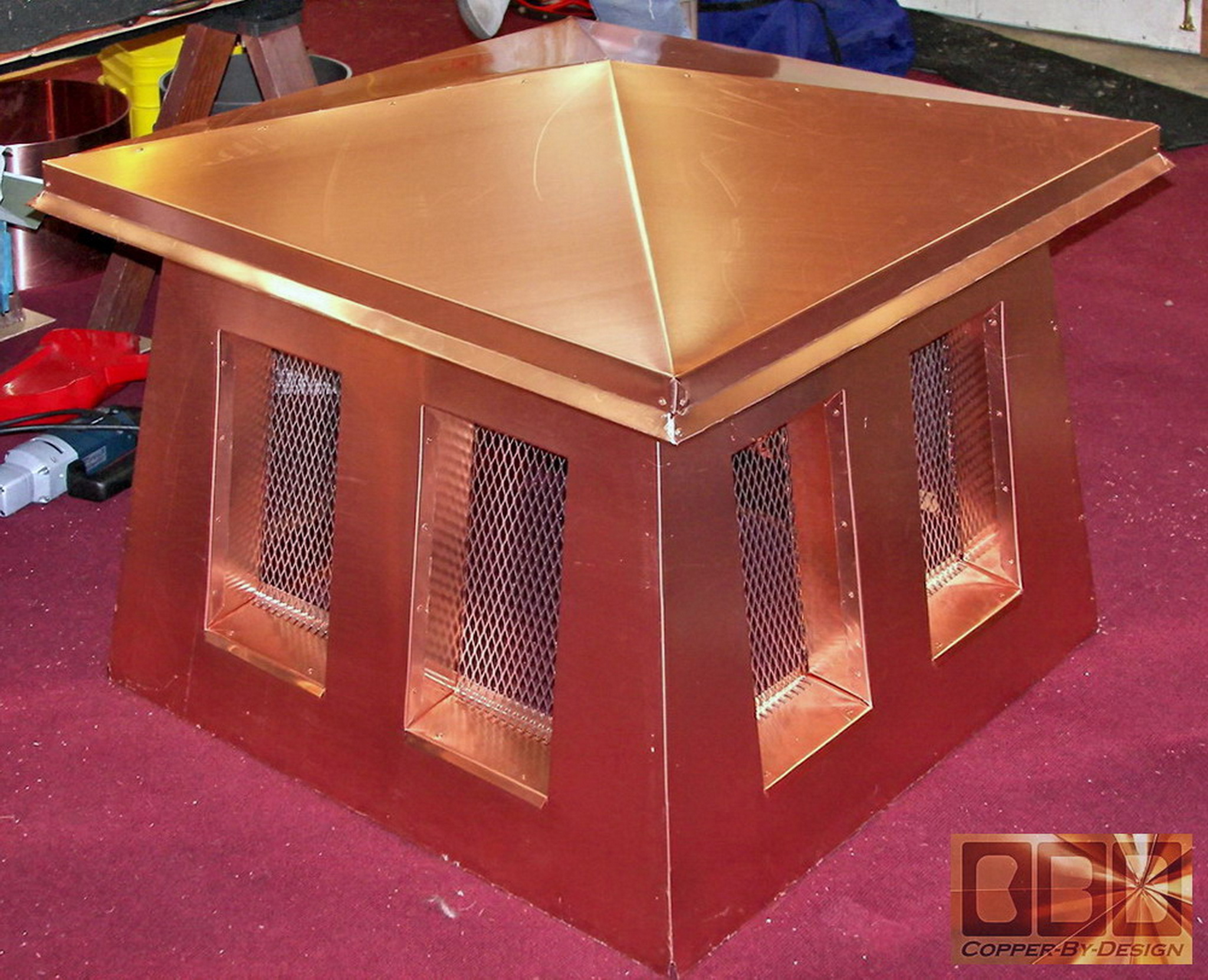
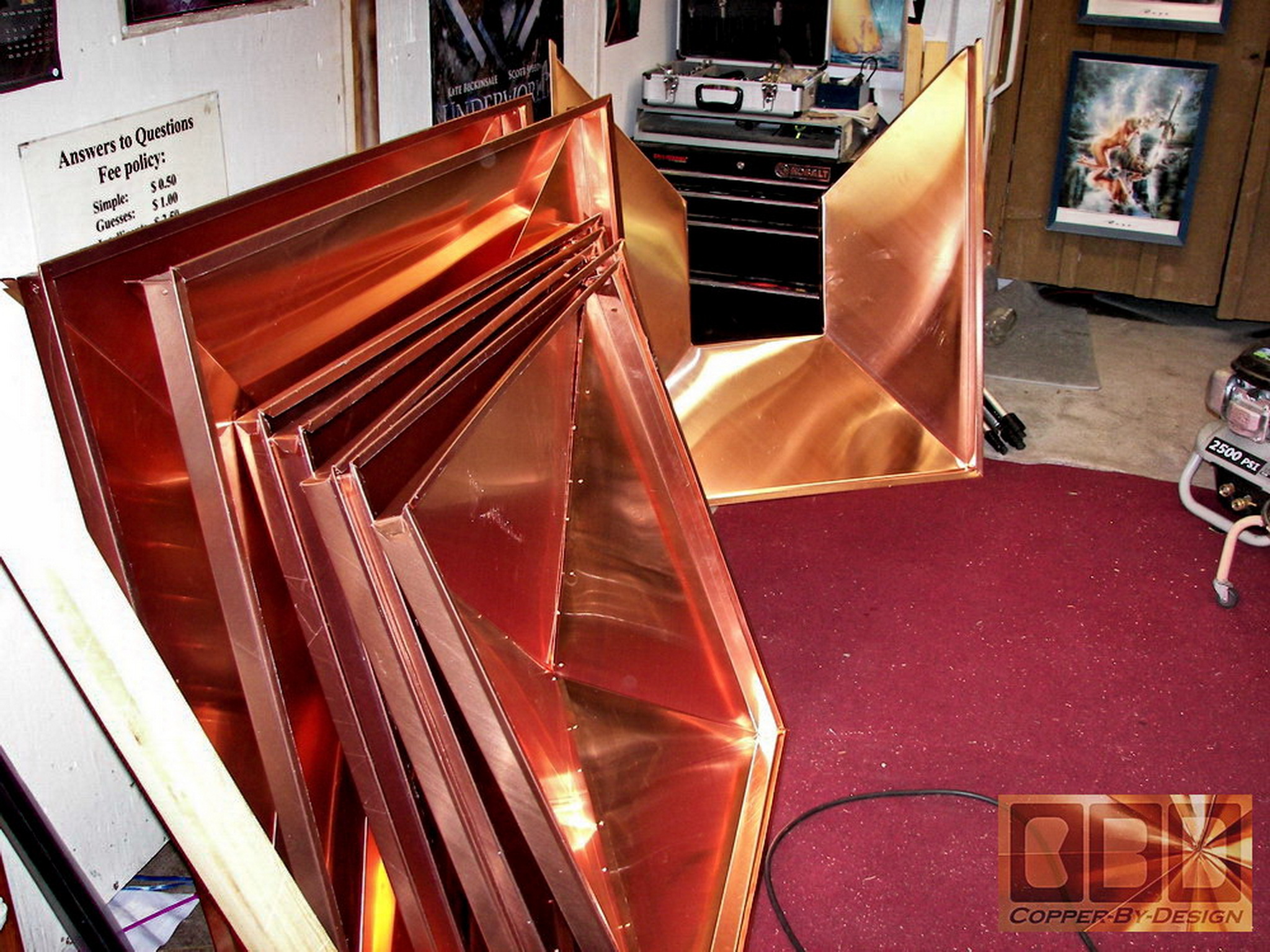
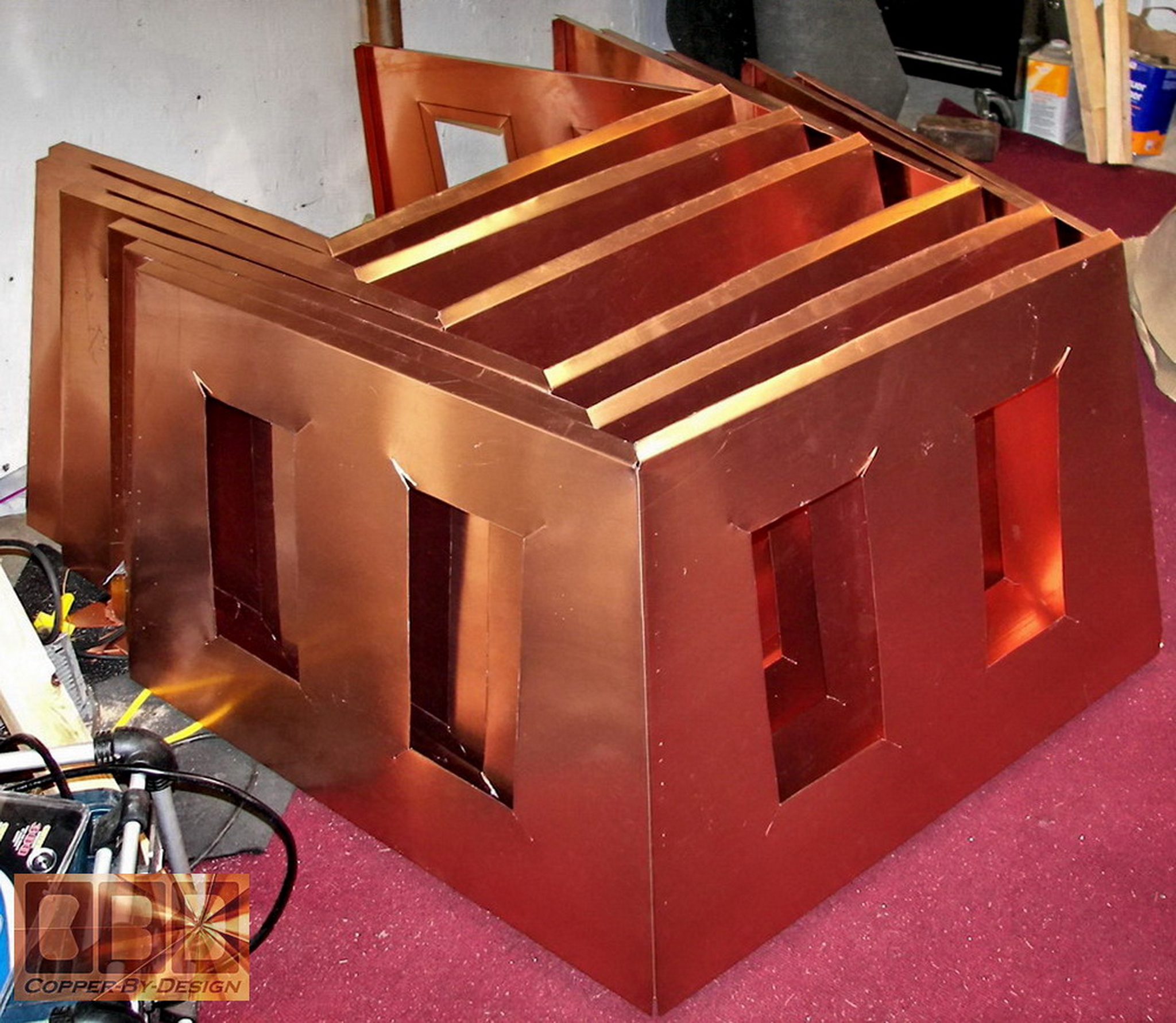
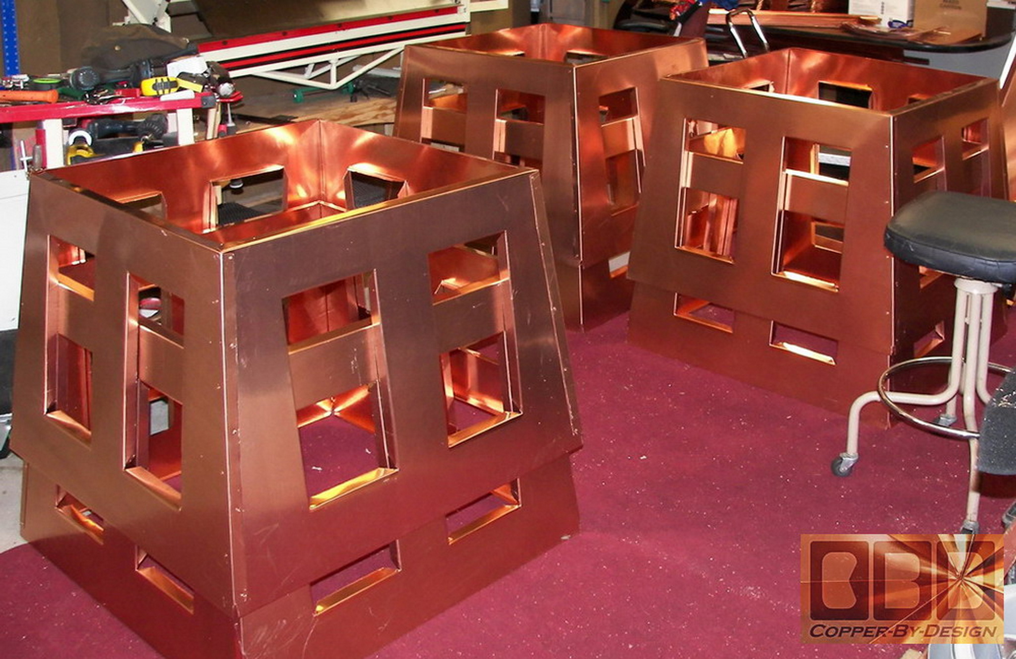
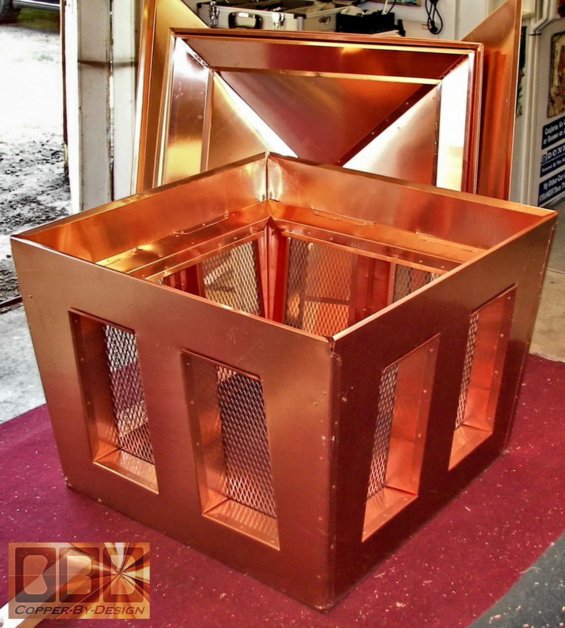
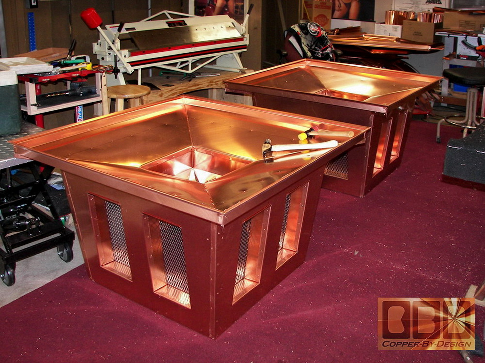
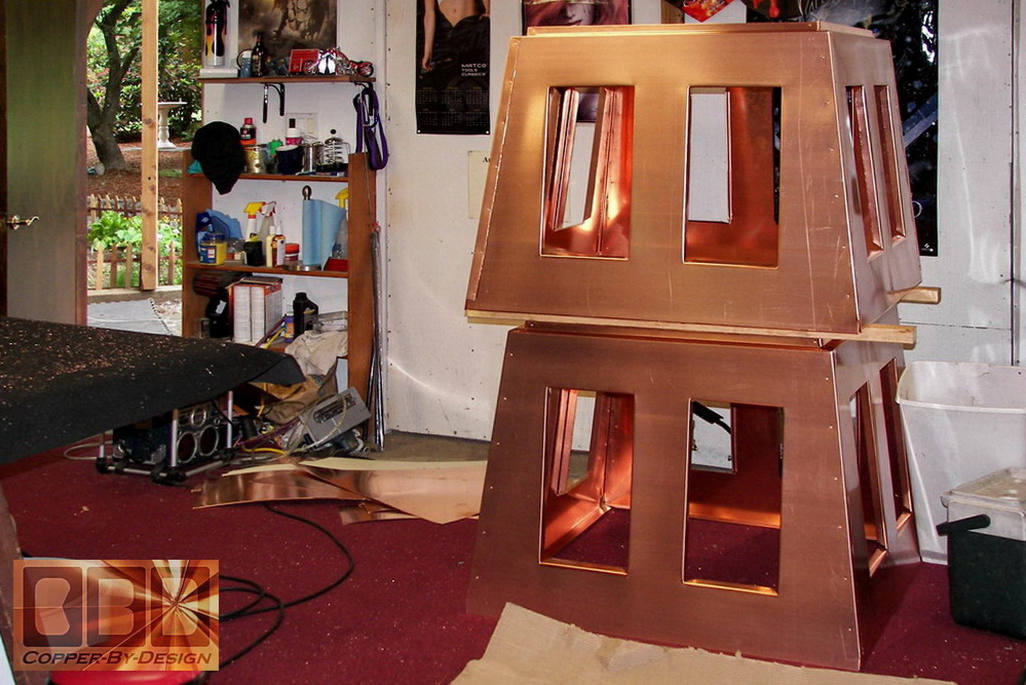
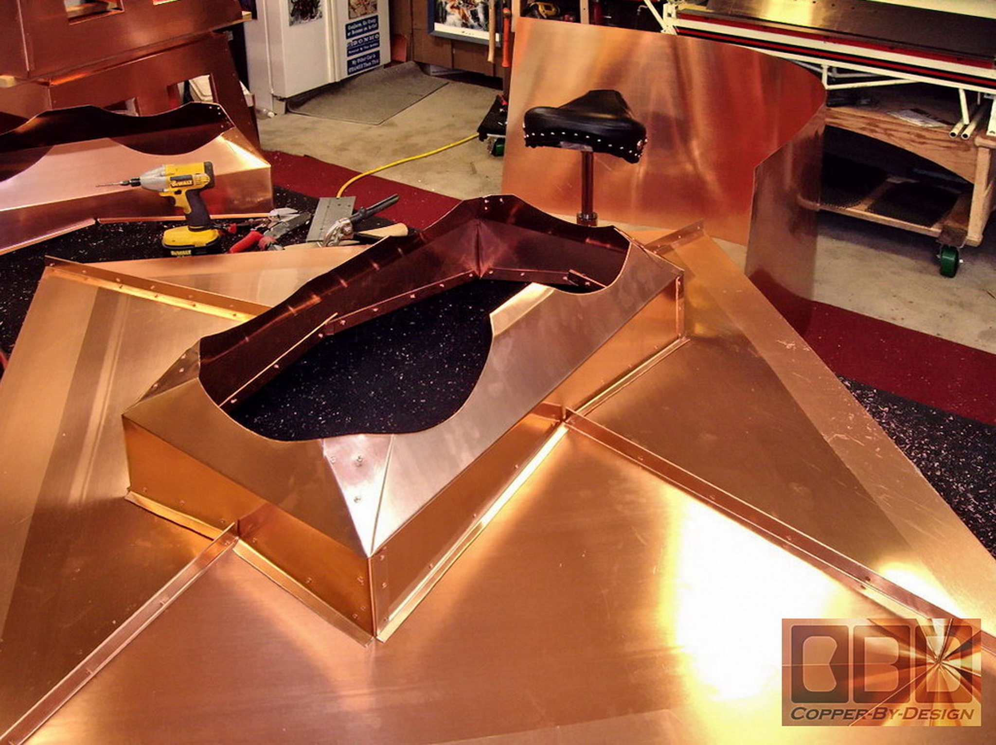
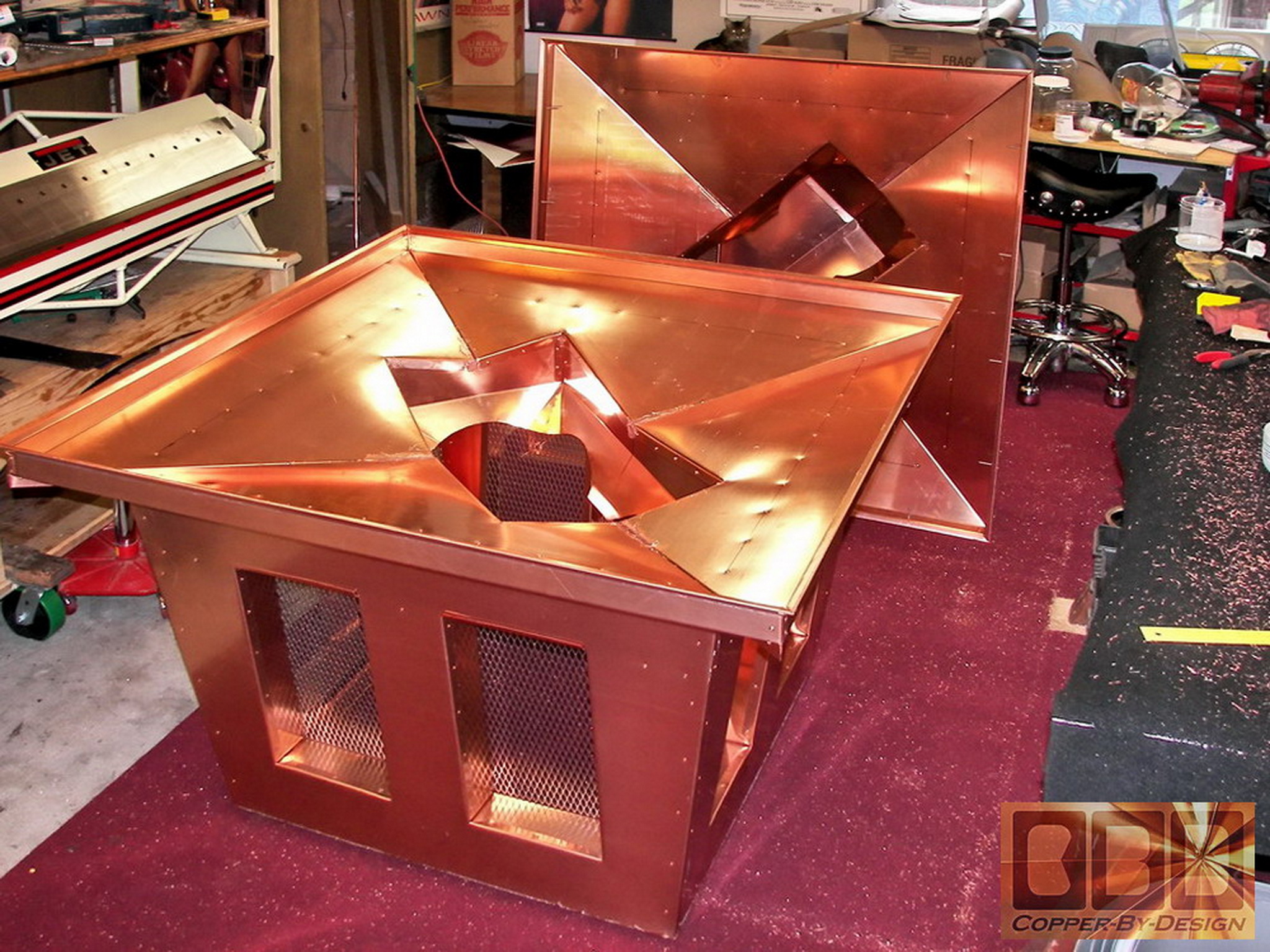
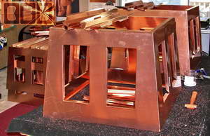
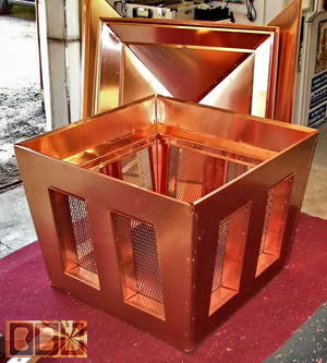
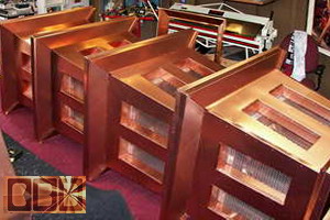
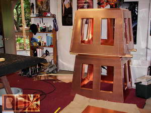
Here is the finished mid-section ready for the
top and bottom to be attached.
Here is several finished mid-sections stacked
up
|
|
Final assembly
and attachment of the pan and roof:
|
|
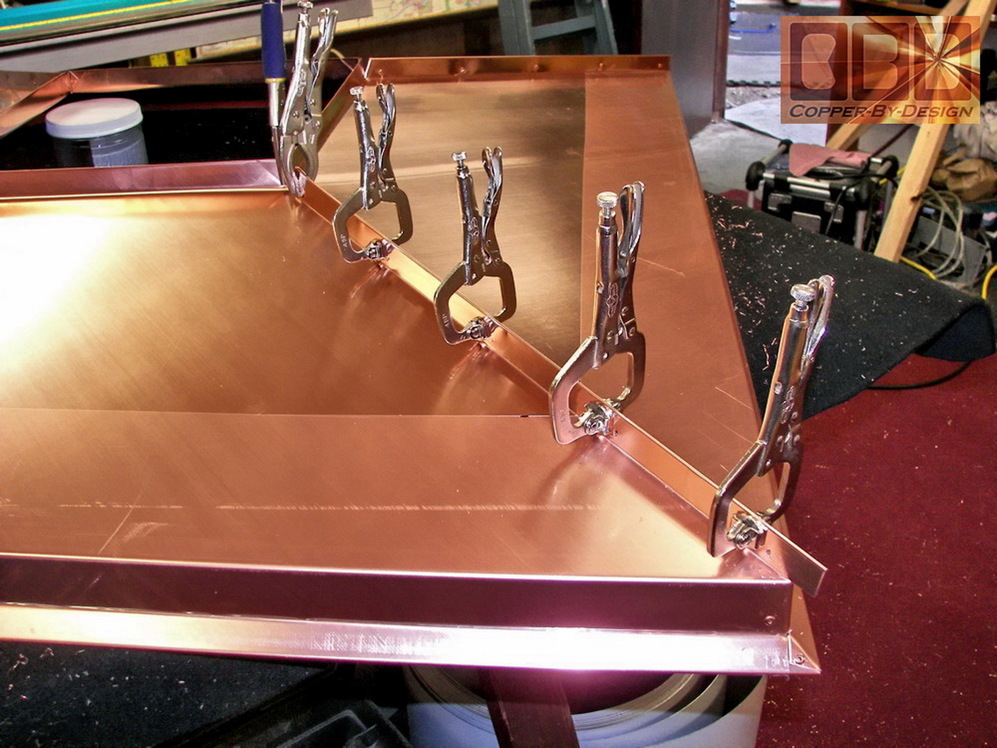
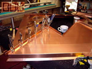
This is a pan being clamped for riveting through
the caped seam. The mid-section upside down to have the pan base attached.
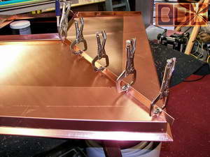 
We have to carefully mark the inside of the pan
for rivet placements. We used 28 rivets to attach each pan.
Here is several more units being worked on.
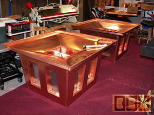 
We only have a small shop, so room is at a premium.
Normally I am not working on more than 1 or 2 projects at a time.
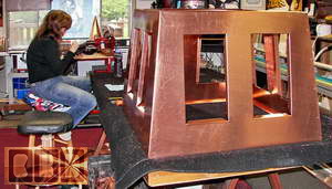
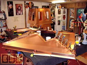
This is the clamping before riveting on the eaves
to the top of the mid-section.
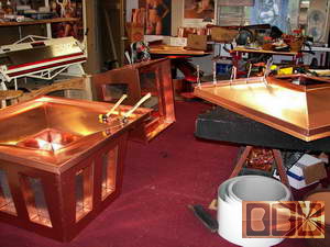
Here is the unit ready for the roof to be fastened
on from several different angels.
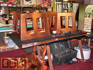
After full assembly we needed a safe place to
store them until we are ready to load them onto the truck for delivery,
but that will be as much as 2 months for the first complete units.
|
|
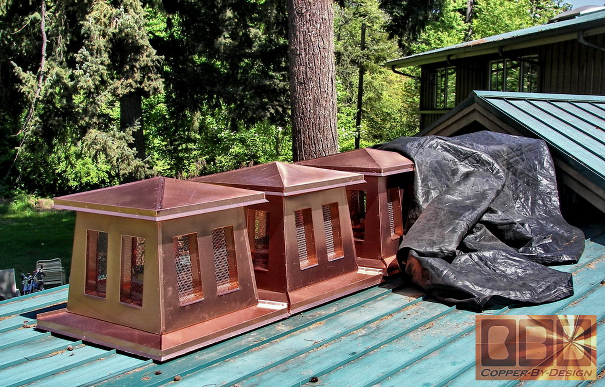
Storing the
assembled units until completion:
|
|
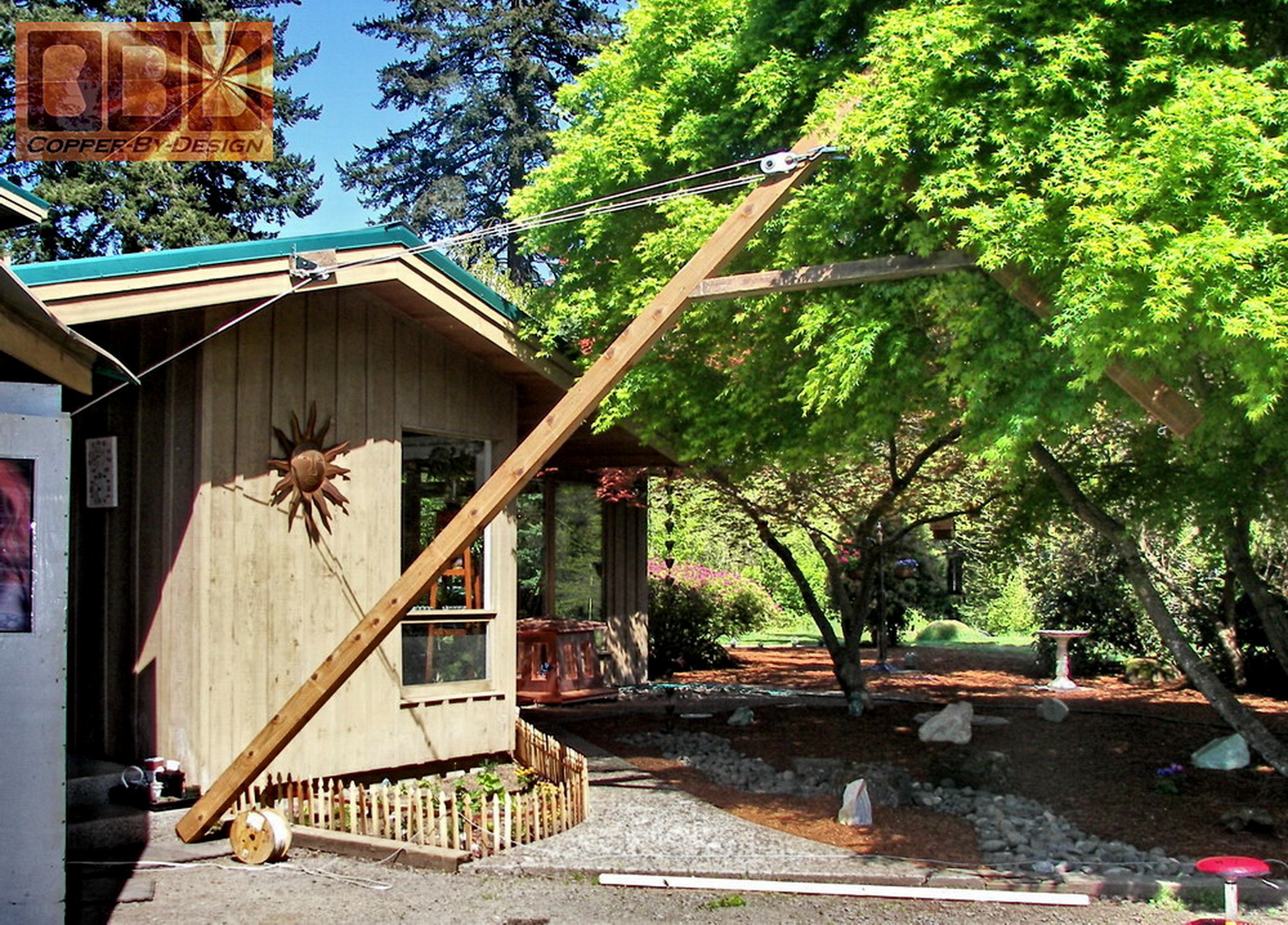
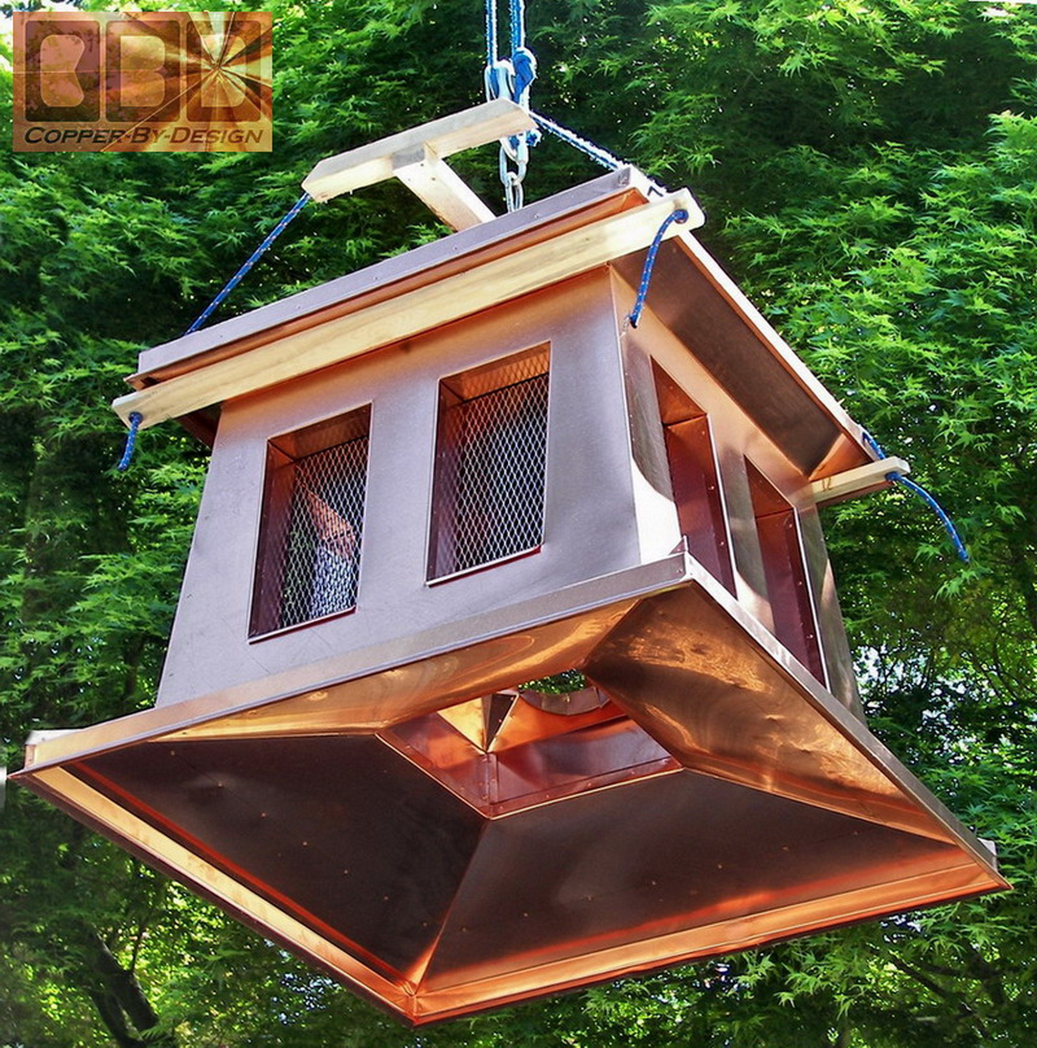
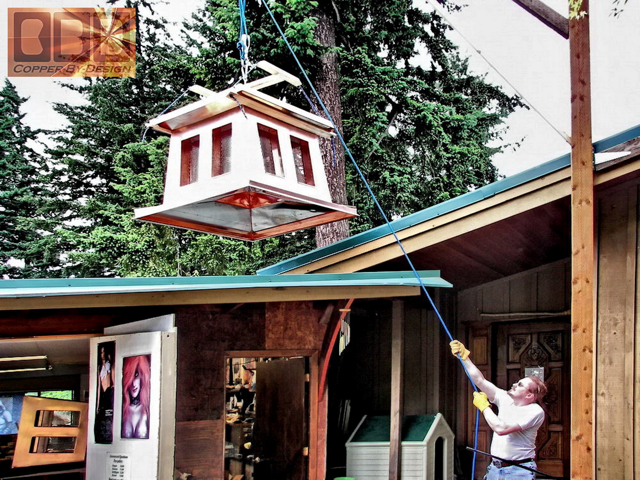
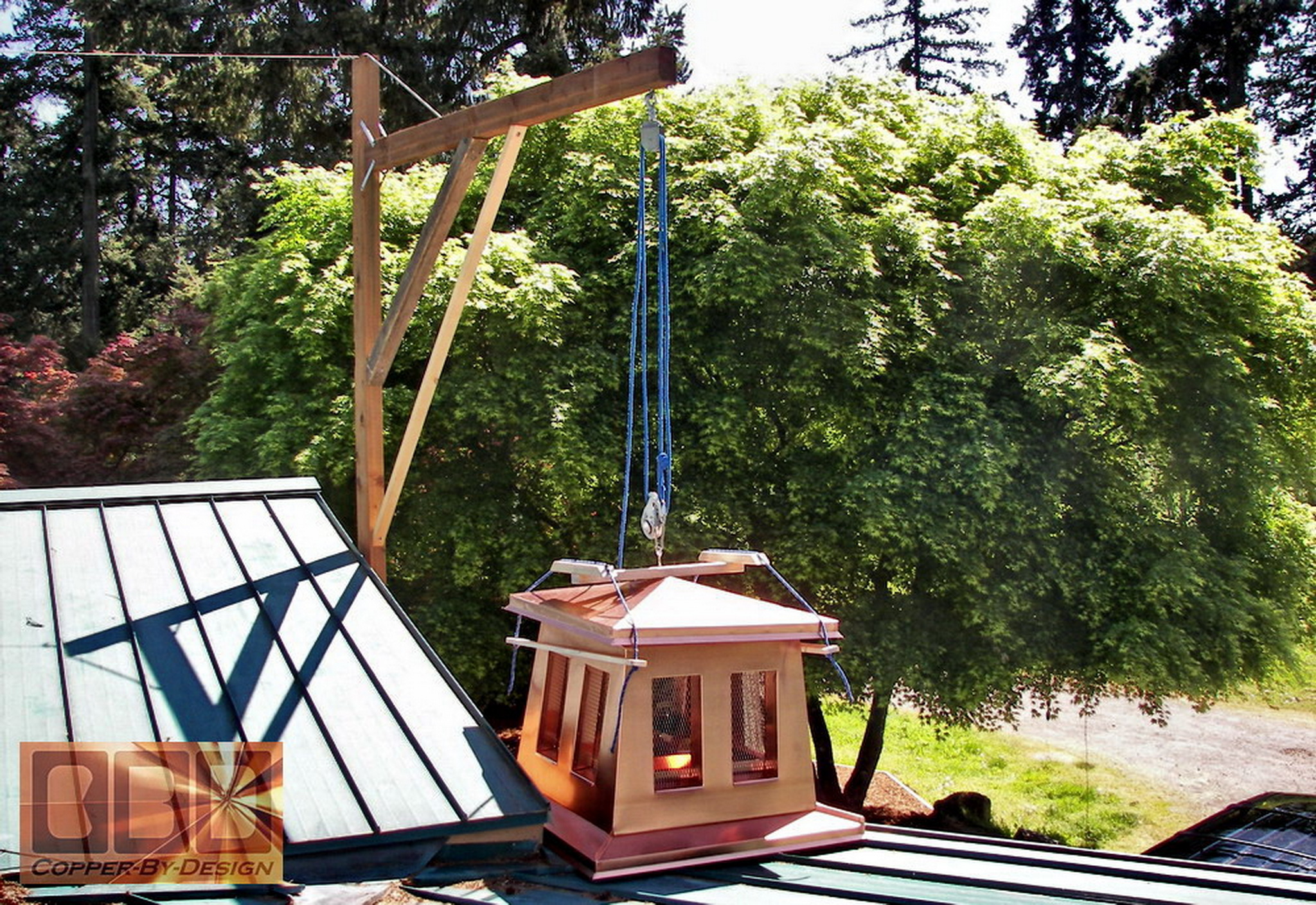
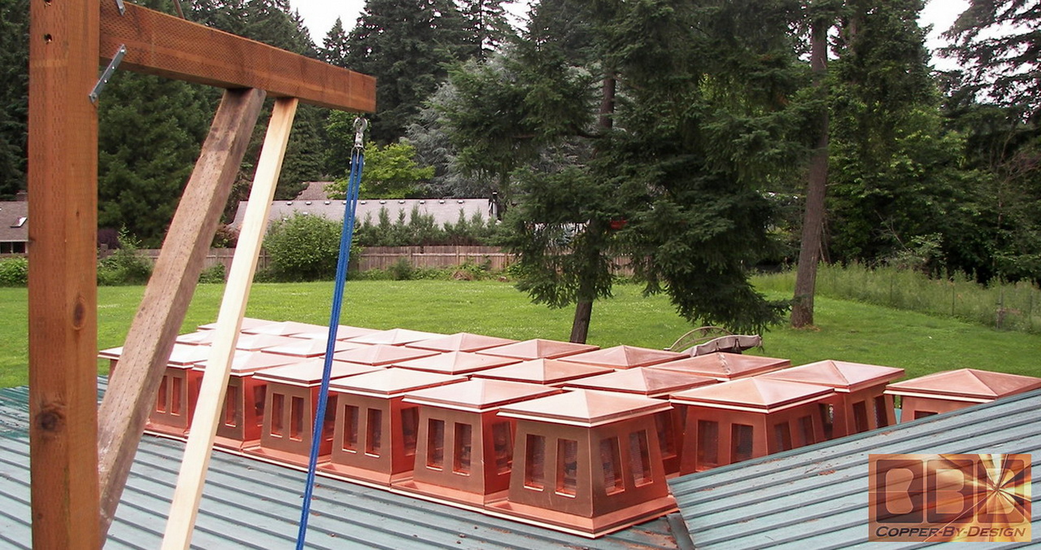
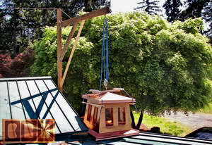
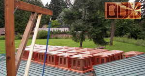
I had to build and mount this hinged crane to
lift them up and swing them over onto the shop's metal roof one at a
time for safe keeping.
 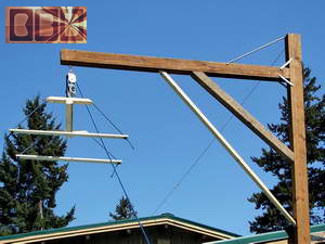
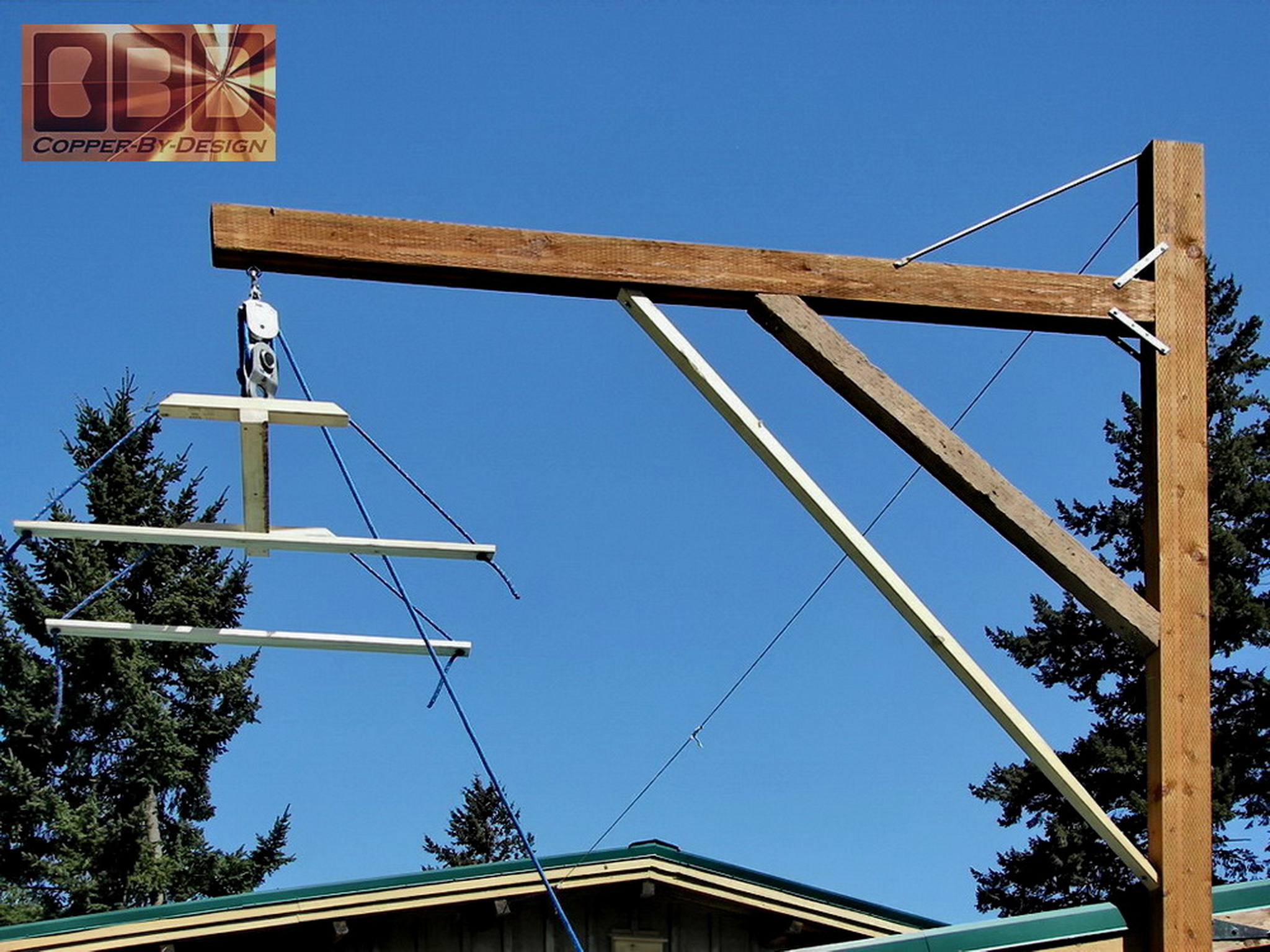
This is the wood frame I made to safely lift them
up on the roof with.
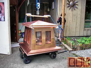 
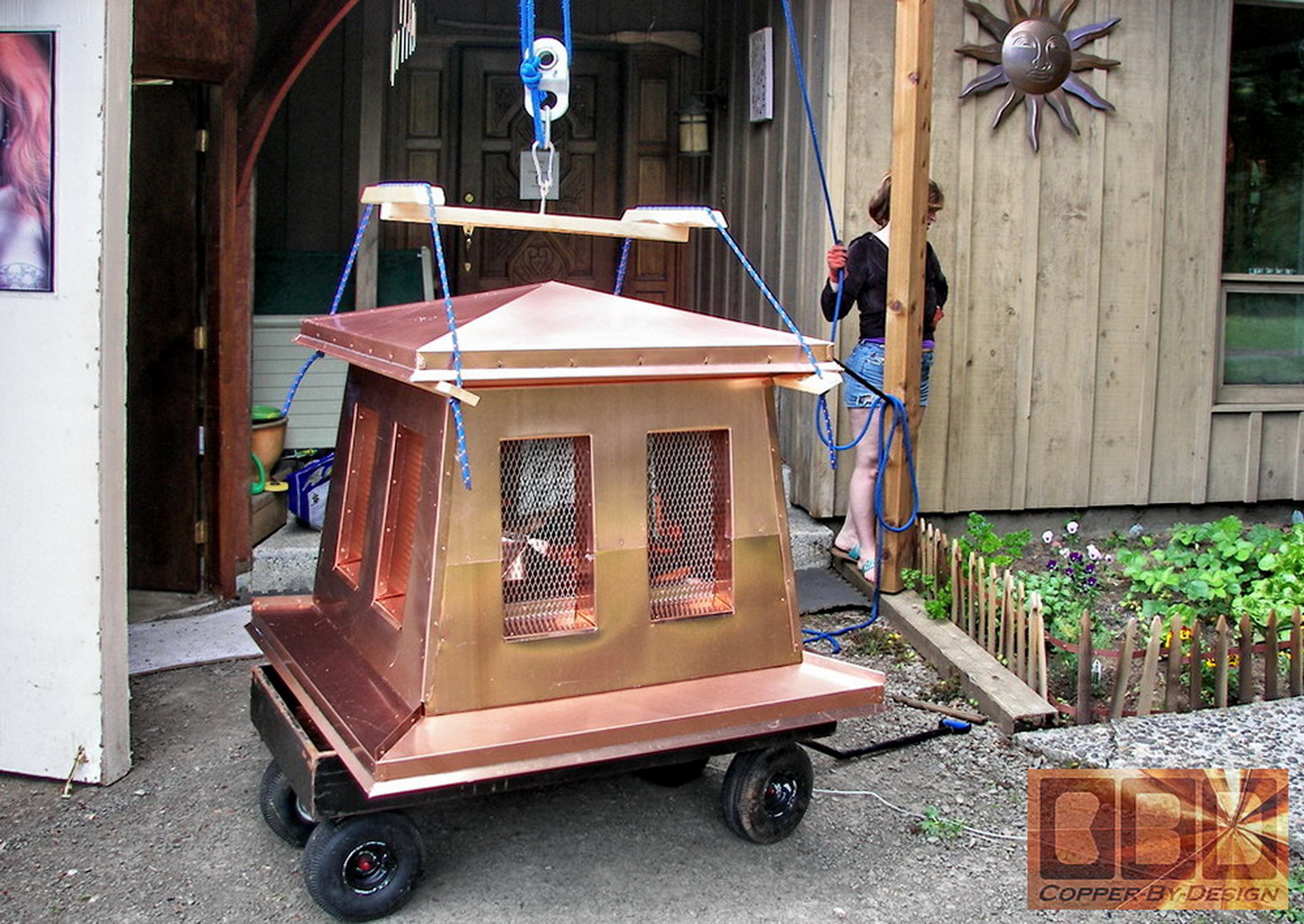
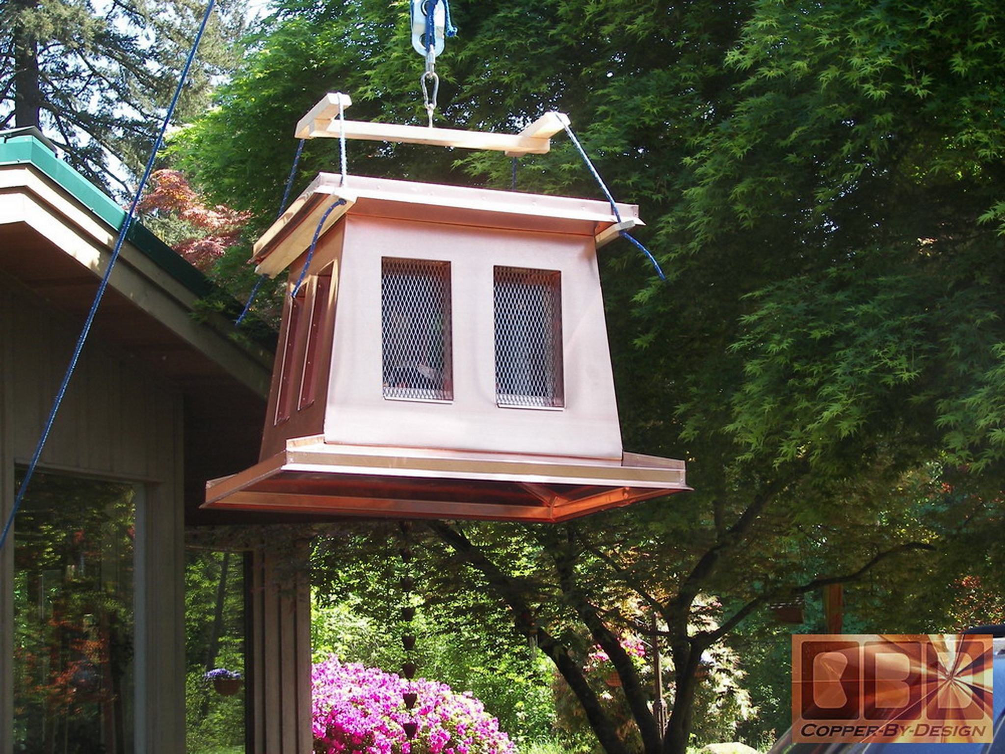
These are photos of them being hoisted up as you
can see. There was a couple pulleys at the top and a nice large one
at the cap to help divide the weight, so I only had to pull 1/3 the
actual weight of the chimney caps.
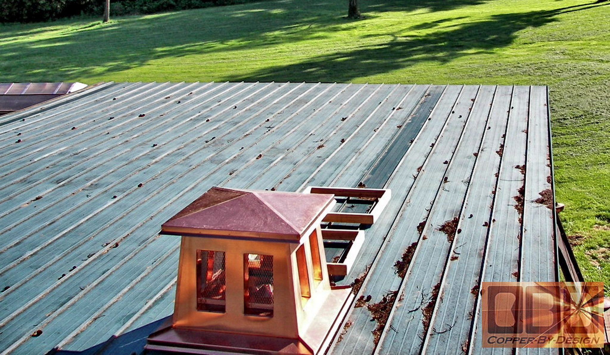
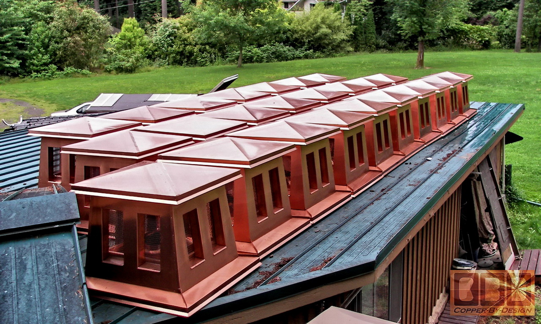
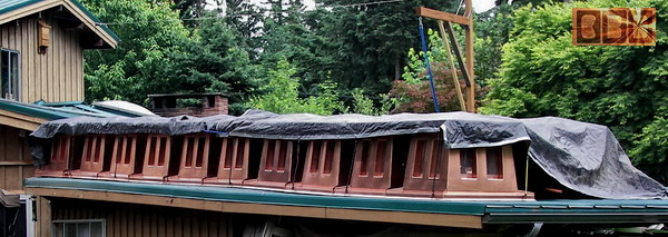
Here it is shown from up on the roof. They were
able to slide easily across the metal roof over the standing seams.
The plastic film made them slide easily. The edges of the pans were
strong enough to hold the weight sitting on only 4 narrow standing seams.
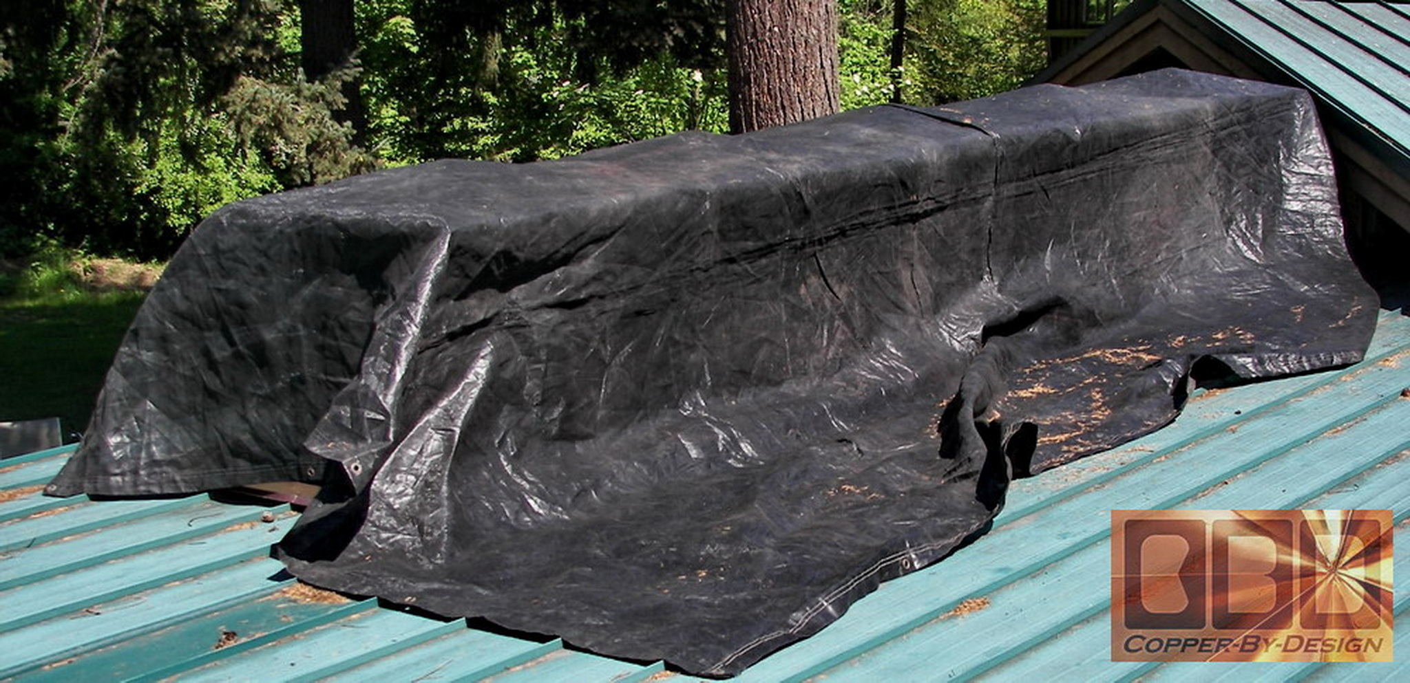
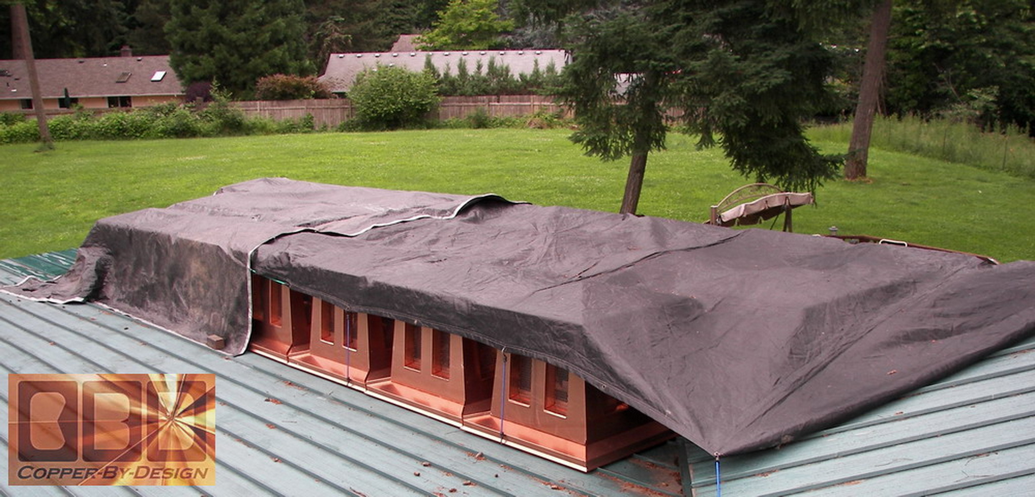
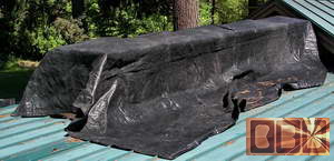
I covered them up with a black nylon tarp to help
keep them clean until we can finish and get them loaded into the truck.
Some had to wait nearly 3 months up there before we got done.
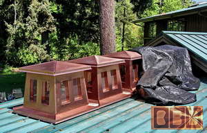 
By the end we had 25 units up there at once. It
was an amazing sight, but made us very nervous to have all that valuable
material up there at the same time!
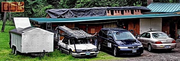
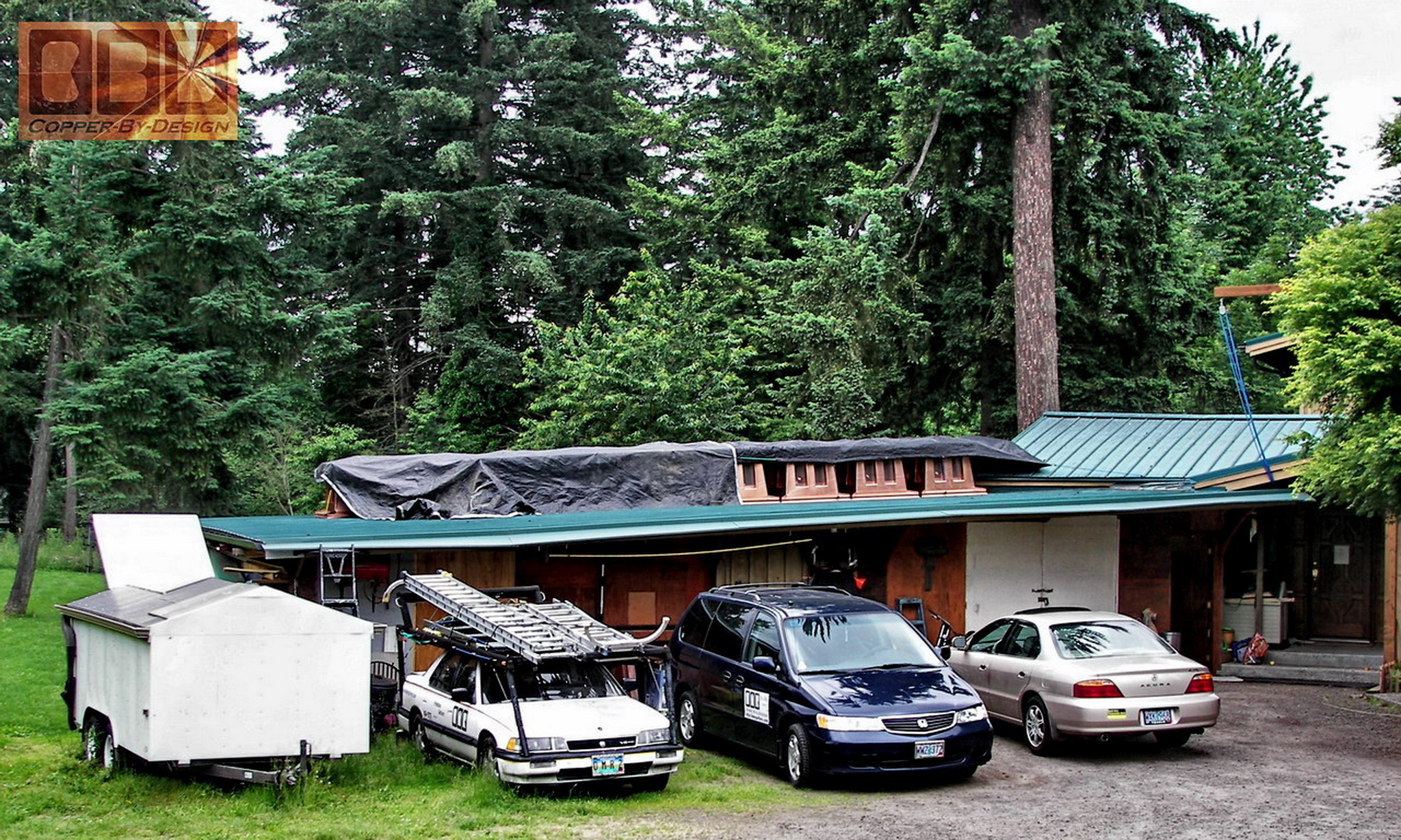
This shows our gutter machine trailer on the left
(with the rear door lifted up), my work car next to it that (used last
10 years, to be decommissioned), the 99 Honda Odyssey van (about to
be converted into my work vehicle), then Tia's 2000 gold Acura TL.
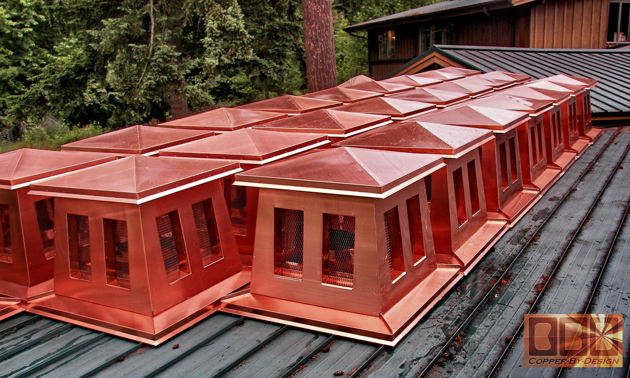
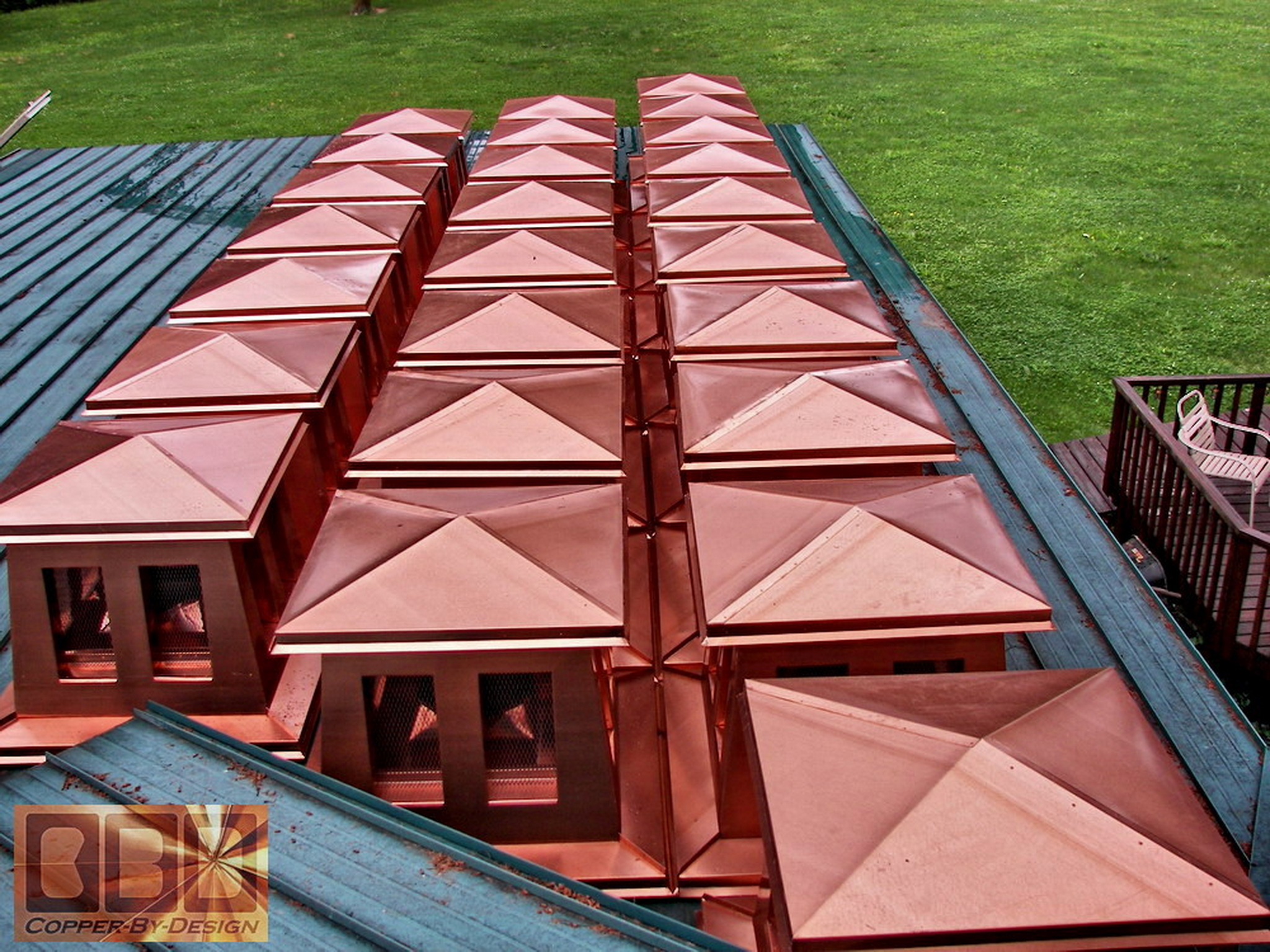
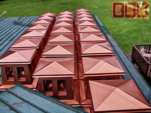
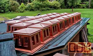
These are photos of the whole set of the 25 single
flue chimney caps from different angles before being removed from the
roof and loaded in the truck.
|
|
The final 2
larger double flue units:
|
|
These are of the mid-section for the 2 larger
double flue units with the clamping before riveting on the cap over
the pan seams. I had to design them to fit the larger chimney tops,
so that means they needed to be larger to scale of the other smaller
units, so they do not look strange.
Here is some photos of the strange double flue
pans we had to design.
This shows the riveting on the pan to the bottom
of the mid-section.
|
|
Loading the
truck:
|
|
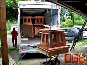
Here is the last work finally finished after 3
long and scary months. If this job went bad, or we got burglarized,
this would have meant financial disaster. Any number of things could
have gone wrong.
 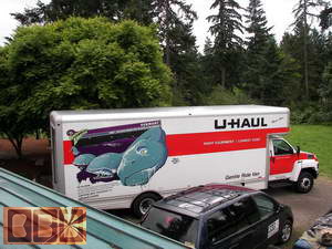
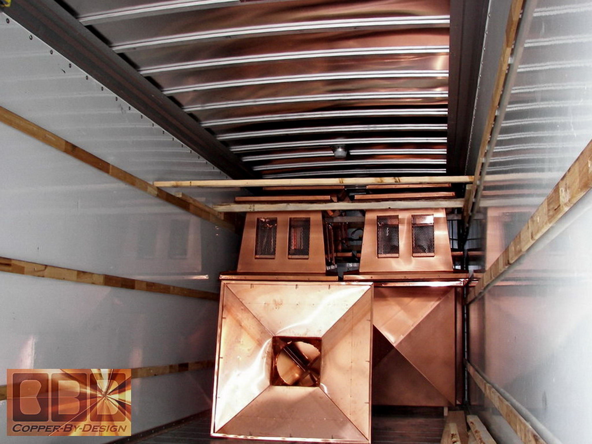
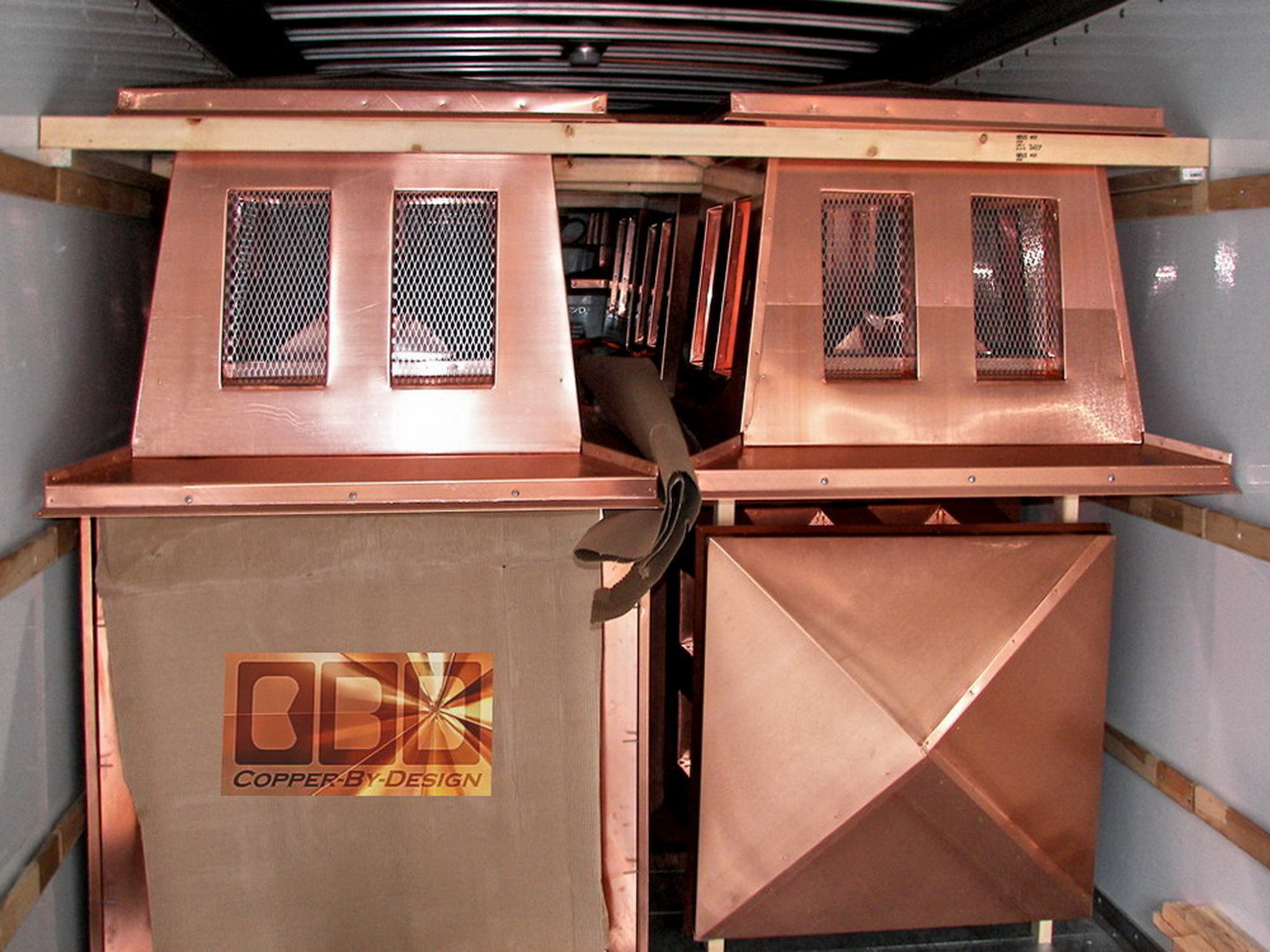
This was the largest truck they rent. I had to
figure out a way to get all these in there safely so nothing would get
damaged, and we did not have much money left for packing material.
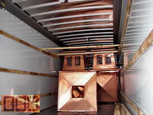 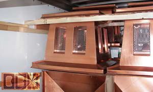
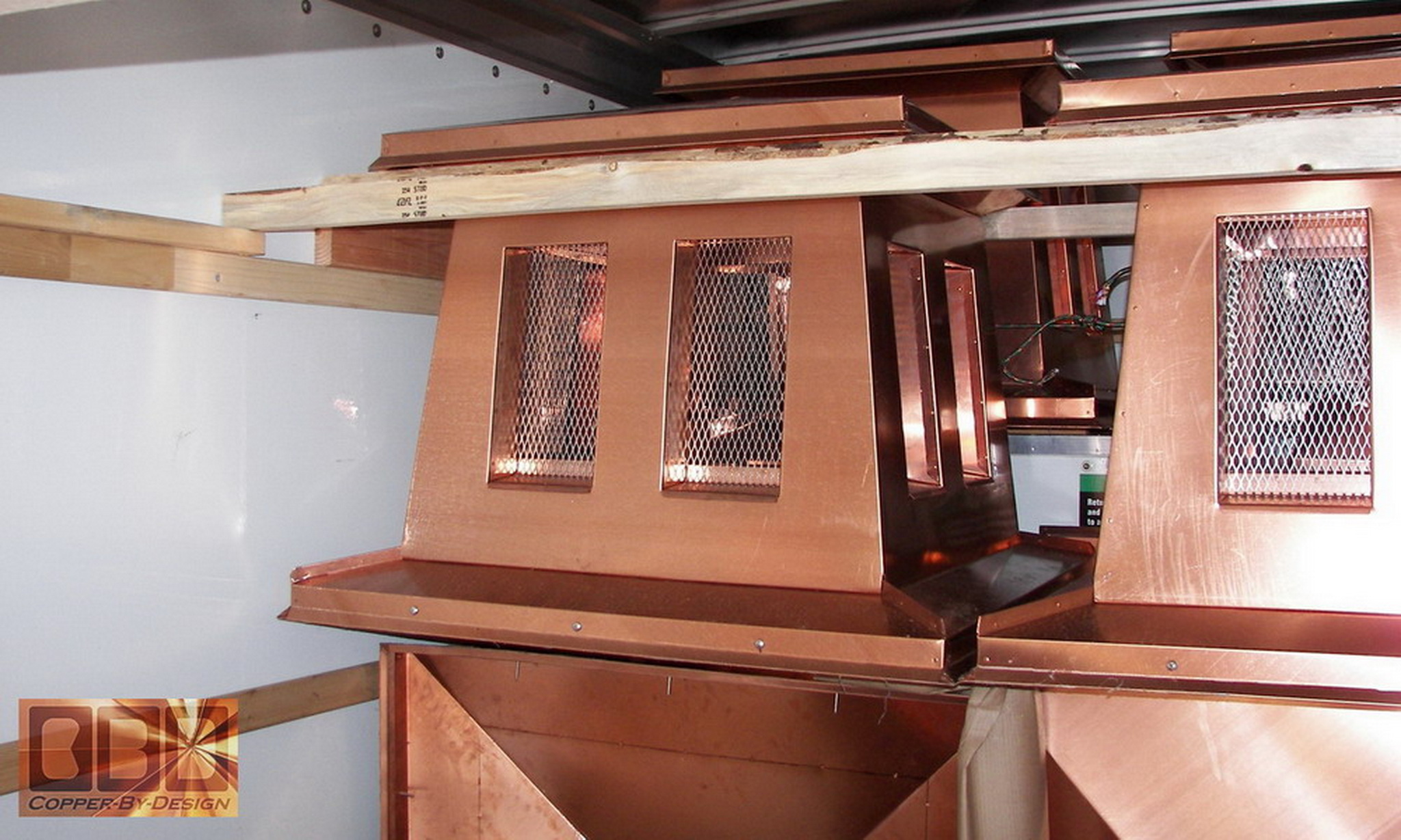
I made these wood rails we would have to leave
behind, since we were flying back. They supported the upper row of chimney
caps from under the roof eaves. Just like how we got them up and down
again from the roof for storage. I felt pretty secure about how strong
they were, but it still made my heart leap out of my chest every time
we hit a bump. I am not sure how it felt back there with all this weight
in the back, but I know we were tossed around up there in the cab.
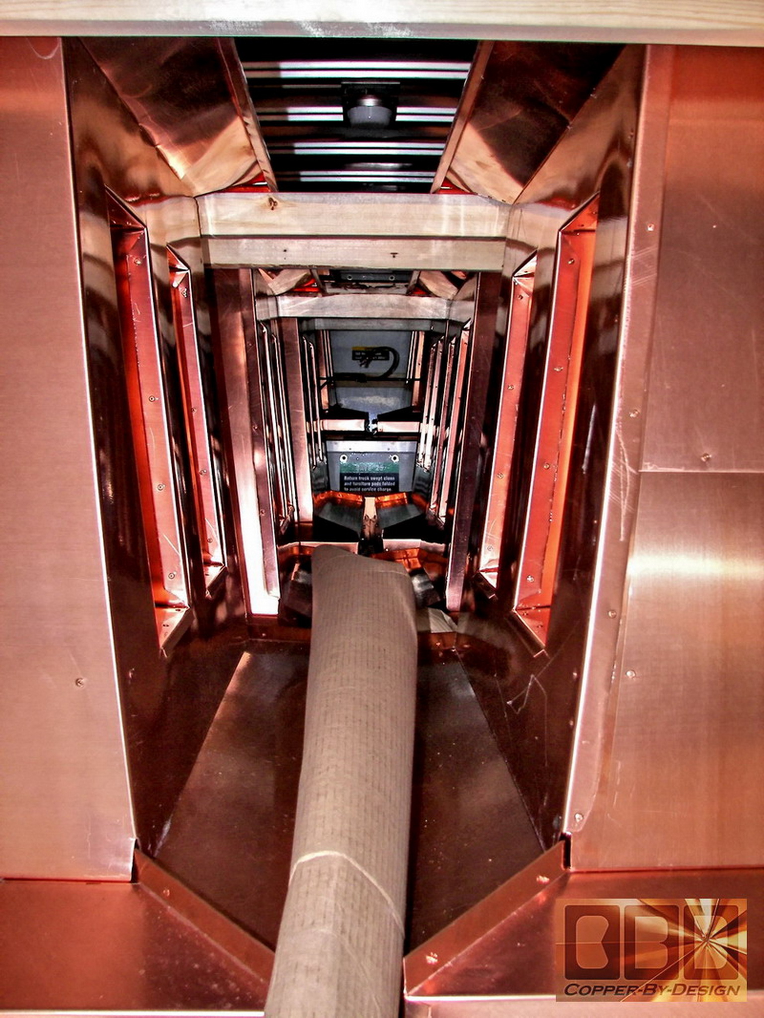
Another concern was if the side wall expanded
in the middle and let the boards drop. We saved the cardboard to pack
between the chimney caps to help keep them from scratching or denting
each other.

|
|
The Tarnished
Units:
|
|
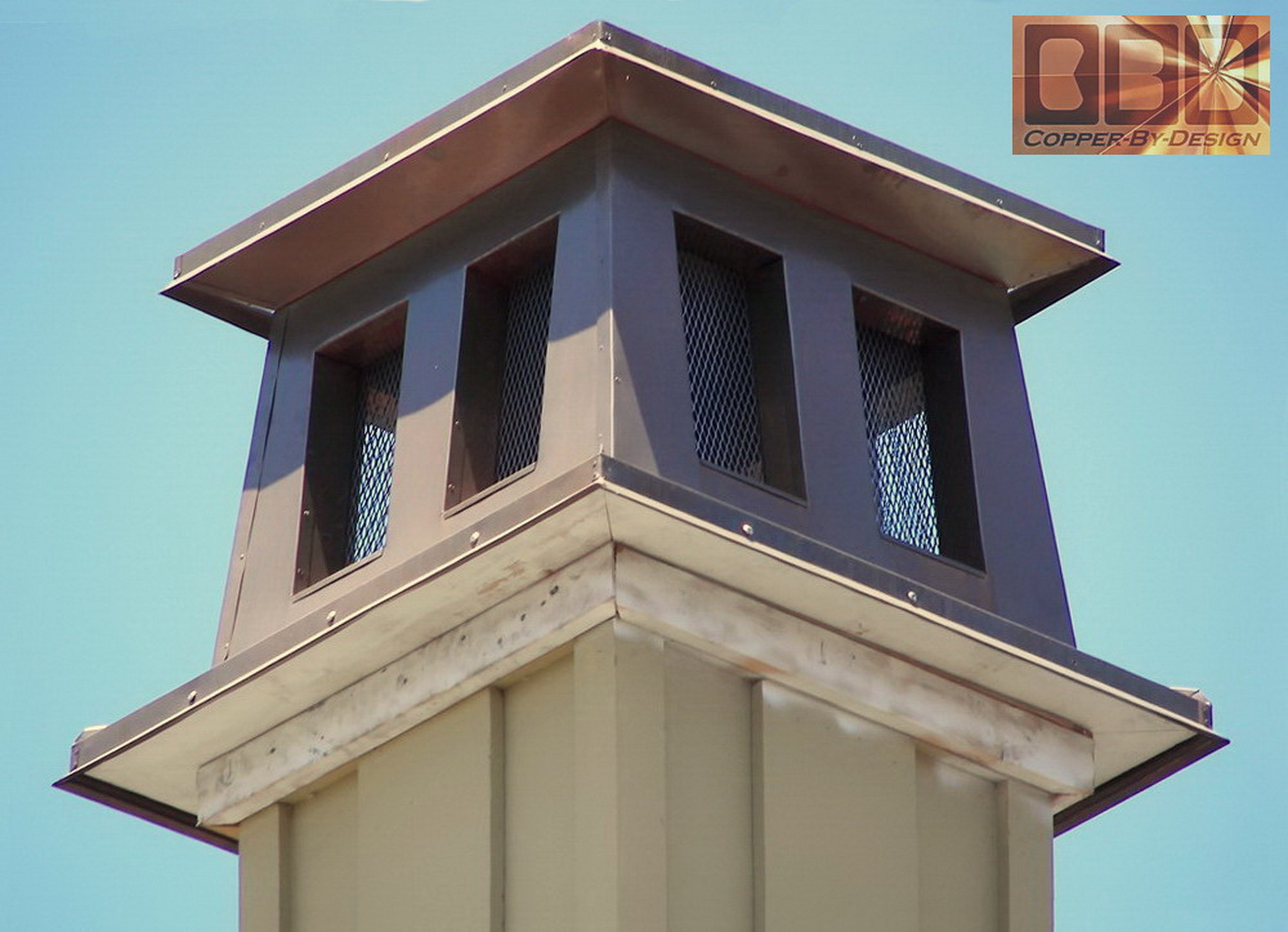
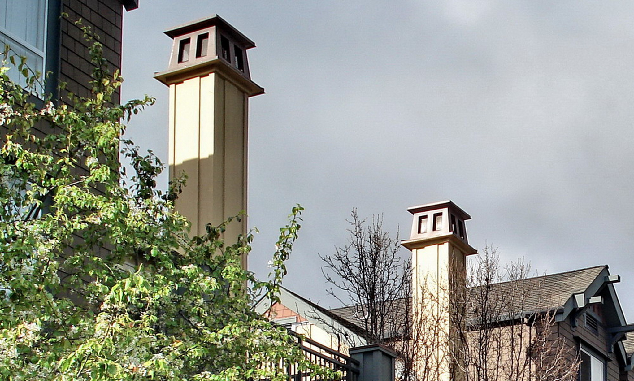
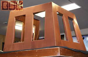
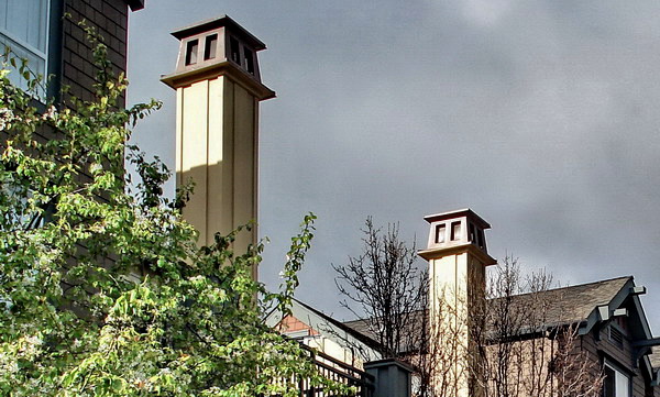
The photos below show the first prototype unit
only 3 months after installation, having turned that satin brown already.
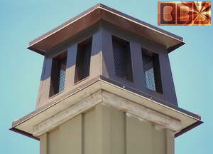 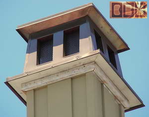
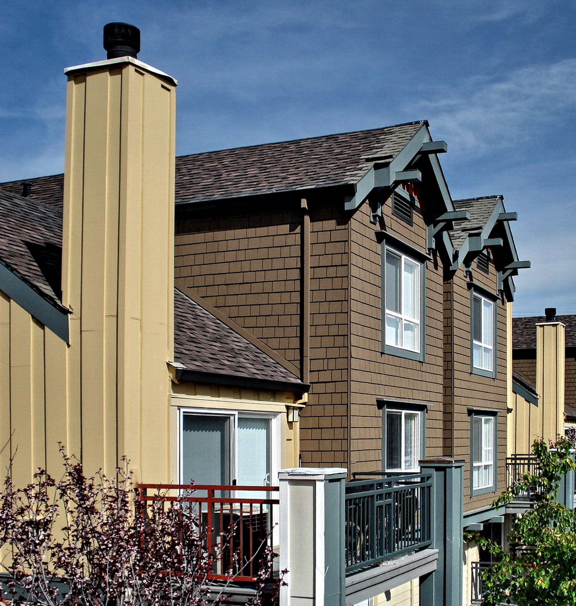
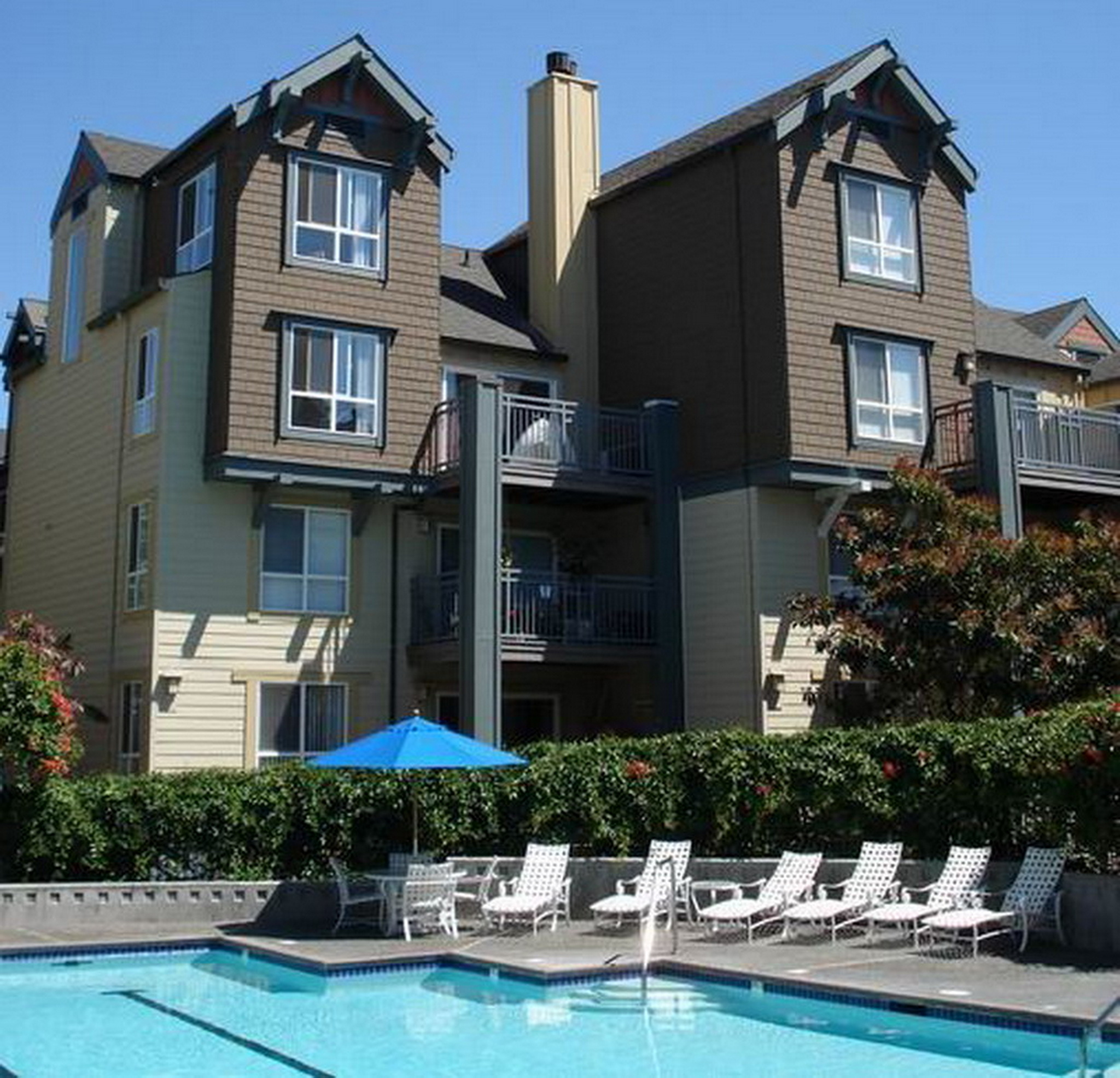
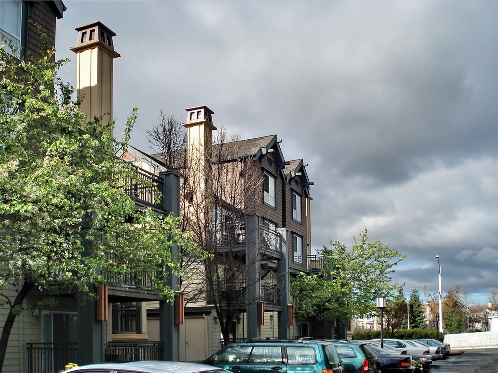
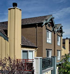
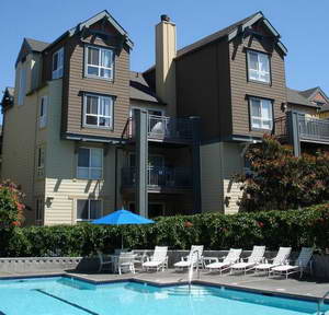
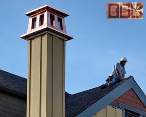
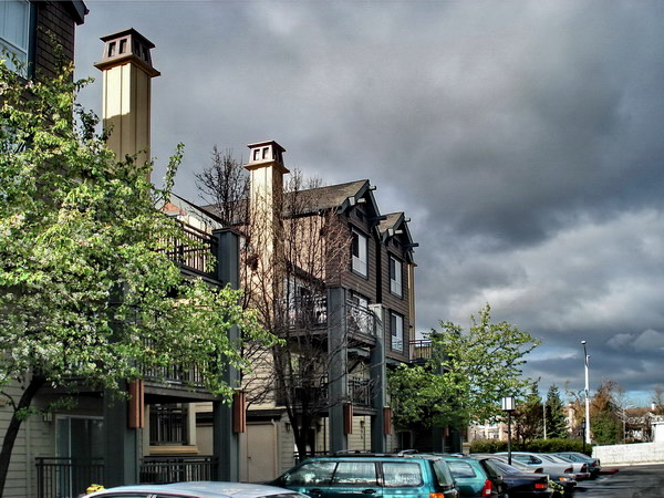
These photos below were sent to us by the client
(3-07) to show a pair of them up in place showing the buildings they
adorn.
|